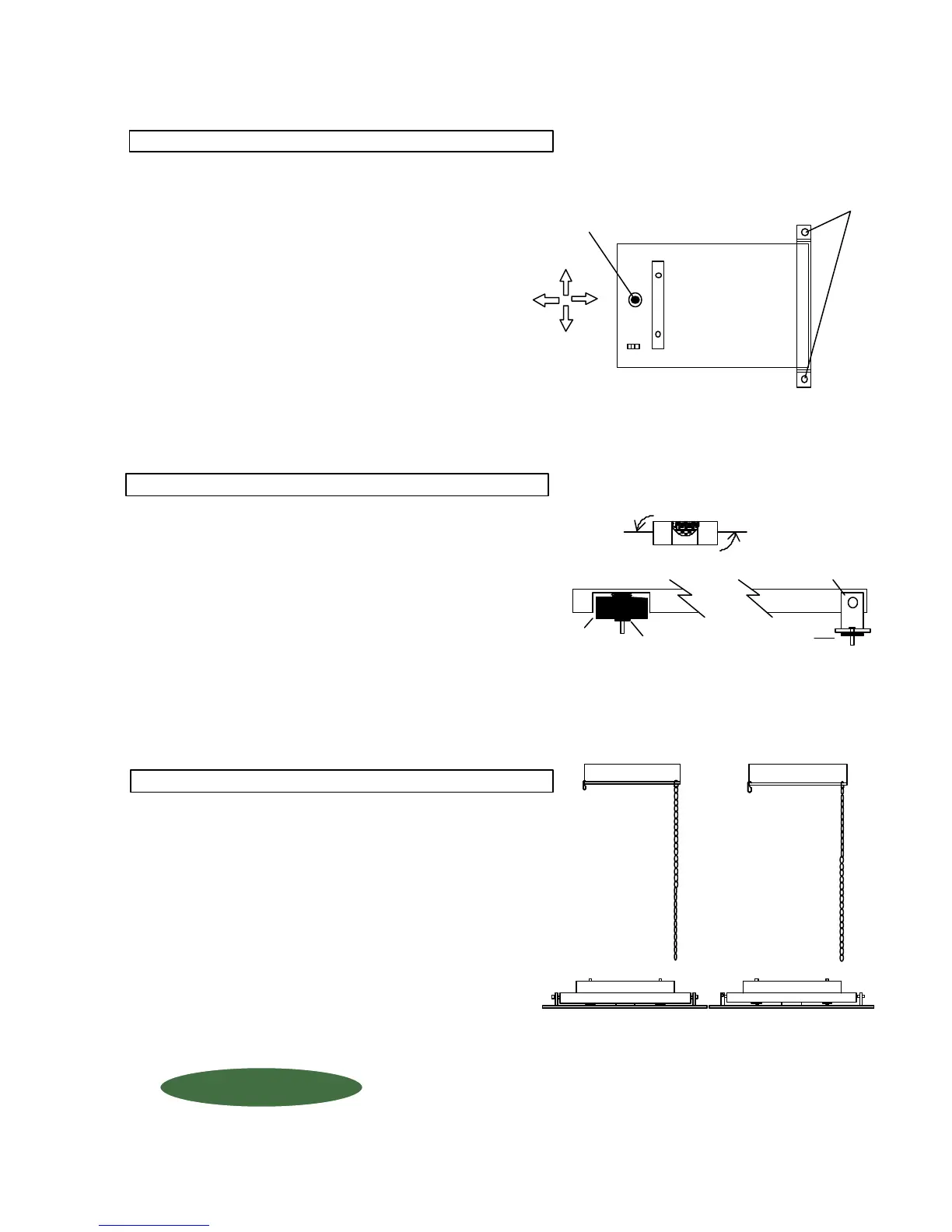
To mount additional scales side-by-side, be sure
to allow for the frame hinge when determining the
distance between platforms (if minimizing floor
area) and repeat Step 1 - 7.
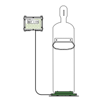
(F) If the "BLACK DOT" on the Load
Cell Button is not centered in the hole
on the platform loosen the floor anchor
bolts slightly and adjust platform as
needed. Once proper alignment is
achieved, tighten the anchor bolts.
Adjust platform for
proper alignment.
Loosen
"BLACK DOT" on
Load Cell should
be centered in hole
on platform.
1150-D Burnett Ave, Concord, CA 94520 USA
1-800-893-6723 US & Canada, Fax: 925-686-6713
www.forceflow.com / info@forceflow.com
File: T4\O&M\CYLWIZ\WIZ150E.tcw (K07.pdf) 1/24/02 BD
FORCE FLOW
FORCE FLOW
F
F
L
L
O
O
Q
Q
I
I
U
U
P
P
W.1.107
S.1.107
Check the platform-mounted level to assure that the
scale is level from FRONT to REAR. If the platform
is not level, either:
(A) RAISE REAR of platform by placing shim(s)
UNDERNEATH the LOAD CELL,
or (B) RAISE FRONT by placing shim(s)
UNDERNEATH the HINGE on the
ANCHOR BOLTS (shims provided with scale).
(B)
LOAD CELL
FRONT
MOUNTING FOOT
PLATFORM
REAR
(A)
STEP 6: LEVEL PLATFORM
LEVELING
SHIMS
(if needed)
LEVELING
SHIMS
(if needed)
STEP 5: ANCHLORING LOAD CELL cont...
STEP 7: MOUNTING ADDITIONAL SCALES
 Loading...