FORCE FLOW
FORCE FLOW
F
F
L
L
O
O
Q
Q
I
I
U
U
P
P
S.1.000
1150-D Burnett Ave, Concord, CA 94520 USA
1-800-893-6723 US & Canada, Fax: 925-686-6713
www.forceflow.com / info@forceflow.com
REF: T4\O&M\INDEX\Y44.tcw etc (Y44.pdf etc)
SECTION
INSTALLATION DRAWINGS
S.1.101-1
S.1.101-2
Single Cylinder Scale, Single Channel Drawing
Dual Cylinder Scale, Dual Channel Drawing
S.2.000
SCALE OPERATION:
S.2.101
Scale Operation (Use "Portable" Applications)
S.3.000
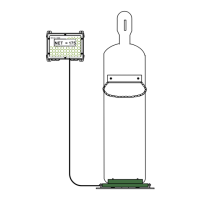
SOLO 1000 Indicator with CHLOR-SCALE 150
INDEX
INSTALLATION CHECK LISTS
S.1.301
S.1.305
1-CHANNEL: Indicator Wiring & Plumbing Drawing
2-CHANNEL: Indicator Wiring etc.
1-CHANNEL: Instructions: Power; Load Cell & Tare Adjust; 4-20mA
2-CHANNEL: Instructions: Power etc.
1-CHANNEL: Instructions: Set Point; Surge & Static Protection
2-CHANNEL: Instructions: Set Point etc.
INDICATOR INSTALLATION
S.1.201-1
S.1.201-2
S.1.202-1
S.1.202-2
S.1.203-1
S.1.203-2
Installation Check List
Start-Up Check List
OPTIONAL ALARM SET POINT:
S.2.301-1
S.2.301-2
1-CHANNEL Alarm Set Point Configuration
2-CHANNEL Alarm Set Point Configuration
PARTS LIST:
S.3.401
Parts List
YOU
ARE
HERE !
Installationn Drawing
Installation Introduction
Installation Steps 1 thru 2
Installation Steps 3 thru 6a
Installation Steps 6b thru 6f
Installation Steps 6g thru 7
INSTALLATION INSTRUCTIONS
S.1.102
S.1.103
S.1.104
S.1.105
S.1.106
S.1.107
 Loading...