INSTALLATION CHECK-OFF LIST
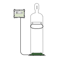
o1 INSTALL SCALE PLATFORM & LOAD CELL (Starting at Section 1.102)
- Route load cell cable to indicator mounting location, per instructions.
o2 MOUNT INDICATOR (Section 1.201)
- Mount at proper location, at “eye level”
o3 WIRE INDICATOR - TURN OFF ALL POWER BEFORE WIRING ! (Section 1.201)
- Connect dedicated clean 110 volt AC power line through 1/2" conduit connector.
- Connect Load Cell cable through 1/4" cord connector.
- Connect 4-20 MA signal through 1/2" conduit connector.
- Connect relays through 1/2" conduit connector (same connector as 4-20 mA)
o 4 SEAL INDICATOR ENCLOSURE TO MAINTAIN 4X RATING !!! (Section 1.201)
- Tighten all four (4) door screws to maintain NEMA 4X seal on box.
- Double check all cord connectors for tight seal.
- Double check all 1/2" conduit connectors for tight seal.
REF: WP File: O&M\SOLOMSTR\ INSTSOLO.wpd (O02.pdf) S.1.301
 Loading...