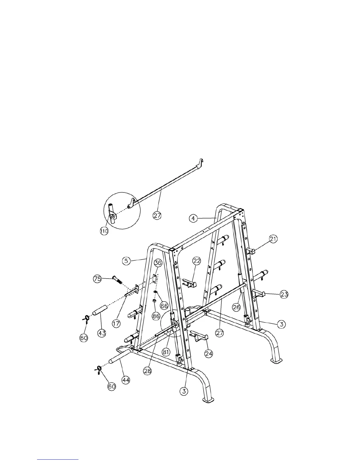
STEP 11 (See Diagram 11)
A.) NOTE: Help of another person is strongly recommended for this step. Place the Lifting
Sleeve (#27) in between the two Safety Stop Frames (#26&110). Align the holes. Insert the
Weight Bar (#28) into the Safety Stop Frame from one end and through the Lifting Sleeve
(#27) to the other Safety Stop Frame on the opposite side. Secure the Weight Bar to each
Safety Stop Frame with two M8 x 3/8” Allen Bolts (#81).
B.) Turn the safety catch hook forward on the Lifting Sleeve to secure its position on the
selected holes on the Front Vertical Frames (#3). Attach a Long Olympic Sleeve (#44) to
each end of the Weight Bar. Attach a Spring Clip (#60) to the Sleeve.
C.) Attach six Weight Posts (#17) to the Left & Right Vertical Frames (#4&5). Secure each
Weight Post with two M10 x 2 ¾” Carriage Bolts (#75), one 4 ¾” x 2” Bracket (#36), two Ø
¾” Washers (#66), and two M10 Aircraft Nuts (#86).
D.) Attach six Olympic Sleeves (#43) to the Weight Posts. Attach Spring Clips (#60) to the
sleeves. Insert the Left & Right Bar Holders (#21 & 22), the Left & Right Safety Catches
(#23 & 24) into the selected holes on the Front Vertical Frames (#3).
20