------------- PART 1 - ENGINE SYSTEMS------------
6. Inspect the relief valve for wear and check for
freedom of movement within the bore. Inspect the
valve bore for excess wear and scoring.
7. Examine the intermediate drive shaft socket ends
for
wear.
S.14635
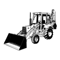
Figure 29
Measuring Oil Pump Clearance
1. Pump Body 3. Inner Rotor
2. Outer Rotor 4. Feeler Gauge
ASSEMBLY
Assembly of the oil pump components follows the
disassembly procedure in reverse. On assembly observe
the following requirements.
• Lubricate all the pump components with clean
engine oil.
• The inner rotor and shaft assembly and the outer
rotor are serviced as an assembly.
• Prior to installation, introduce clean engine oil in-
to the inlet port and rotate the pump shaft by
hand.
INSTALLATION
Installation of the oil pump follows the removal pro-
cedure in reverse. On installation observe the follow-
ing requirements.
14
• Install a new gasket and tighten the bolts to the
correct torque, see "Specifications," Chapter 3.
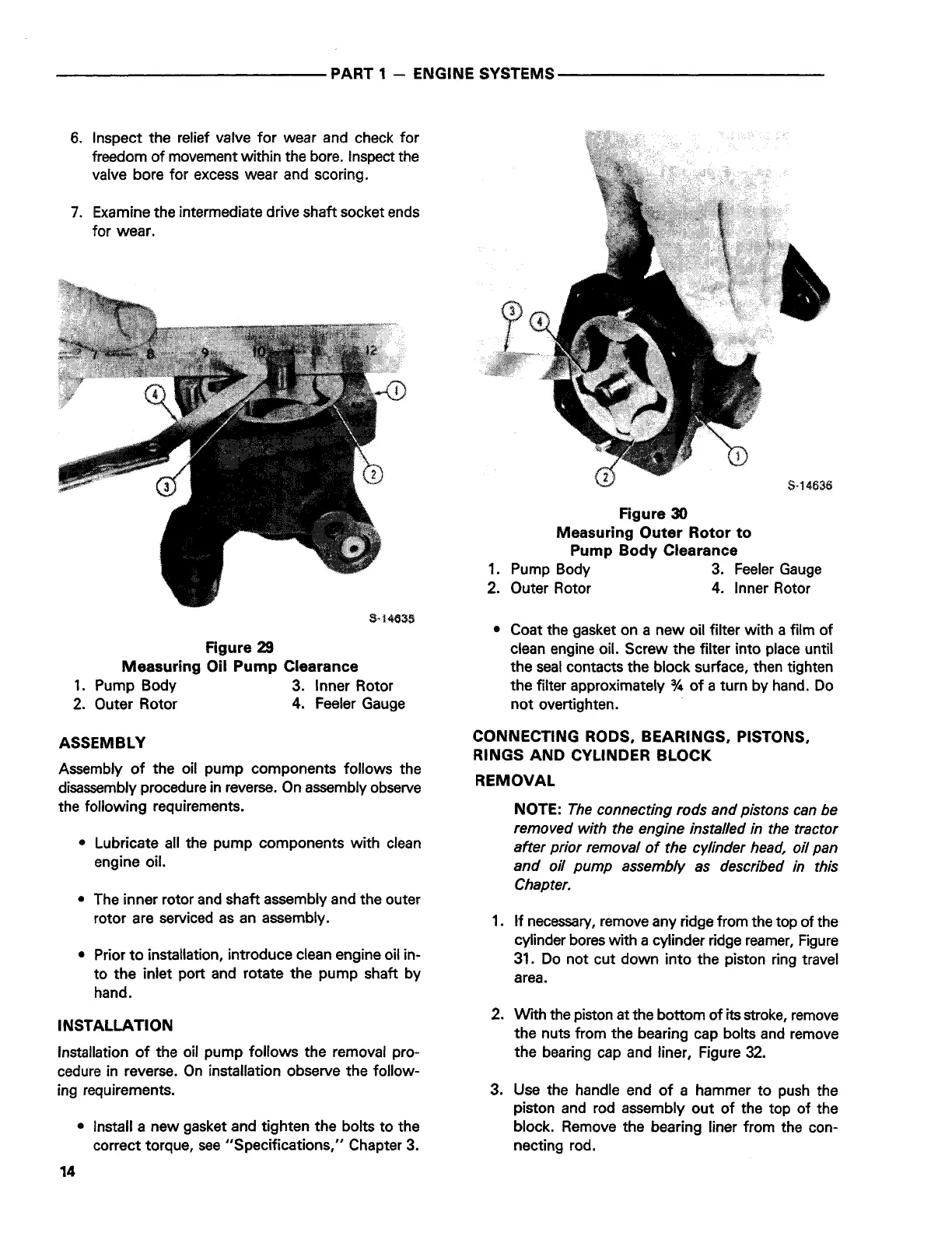
Figure 30
Measuring Outer Rotor to
Pump Body Clearance
1. Pump Body 3. Feeler Gauge
2. Outer Rotor 4. Inner Rotor
• Coat the gasket on a new oil filter with a film of
clean engine oil. Screw the filter into place until
the seal contacts the block surface, then tighten
the filter approximately
¾ of a turn by hand. Do
not overtighten.
CONNECTING RODS, BEARINGS, PISTONS,
RINGS AND CYLINDER BLOCK
REMOVAL
NOTE:
The connecting rods and pistons can be
removed with the engine installed in the tractor
after prior removal of the cylinder head, oil pan
and oil pump assembly as described in this
Chapter.
1. If necessary, remove any ridge from the top of the
cylinder bores with a cylinder ridge reamer, Figure
31. Do not cut down into the piston ring travel
area.
2. With the piston at the bottom of its stroke, remove
the nuts from the bearing cap bolts and remove
the bearing cap and liner, Figure 32.
3. Use the handle end of a hammer to push the
piston and rod assembly out of the top of the
block. Remove the bearing liner from the con-
necting rod.
 Loading...