PART 2-2 - Brake System
2-15
TO VACUUM
POWER UNIT
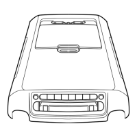
FIG. 10—Parking Brake Control Assembly—Manual Release
park position with the engine running,
or in any position with the engine off.
The power unit piston rod is at-
tached to the release lever. Since the
release lever pivots against the pawl,
a slight movement of the release lever
will disengage the pawl from the rat-
chet allowing the brakes to release.
NEUTRAL
SAFETY SWITCH
(VACUUM RELEASE VALVE)
TO ENGINE
MANIFOLD
VACUUM
H1286-A
VACUUM
JUNCTION BLOCK
FIG.
11—
Connections for
Automatic Parking Brake Release
The release lever pivots on a rivet pin
in the pedal mount (Fig. 9).
The vacuum power unit with
mounting bracket is riveted to the
control assembly. The vacuum actu-
ated piston within the unit is con-
nected by a rod to the upper end of
the release lever to move the pawl out
of engagement with the ratchet (Fig
9).
The lower end of the release lever
extends out for alternate manual re-
lease in the event of vacuum power
failure or for optional manual release
at any time.
Hoses connect the power unit and
the engine manifold to a vacuum re-
lease valve in the transmission neu-
tral safety switch (Fig. 9 and 10).
Moving the transmission selector le-
ver into any drive position with the
engine running will open the release
valve to connect engine manifold vac-
uum to one side of the actuating pis-
ton on the power unit (Fig. 12). The
pressure differential thus created will
cause the piston and link to pull the
release lever.
IN-VEHICLE ADJUSTMENTS AND REPAIRS
After any brake service work, ob-
tain a firm brake pedal before mov-
ing the vehicle. Riding the brake
pedal (common on left foot applica-
tion) should be avoided when driving
the vehicle.
BRAKE SHOE ADJUSTMENTS
The hydraulic service brakes are
self-adjusting and require a manual
adjustment only after the brake shoes
have been relined, replaced, or when
the length of the adjusting screw has
been changed while performing some
other service operation. The manual
adjustment is performed with the
drums removed, using the tool and
the procedure detailed below.
When adjusting the rear brake
shoes,
check the parking brake cables
for proper adjustment. Make sure
that the equalizer operates freely.
To adjust the brake shoes:
1.
Use Rotunda Tool HRE 8650,
(Fig. 12) to determine the inside di-
ameter of the drum braking surface.
2.
Reverse the tool as shown in
Fig. 13 and adjust the brake shoe
diameter to fit the gauge. Hold the
automatic adjusting lever out of en-
gagement while rotating the adjust-
ing screw, to prevent burring the
screw slots. Make sure the adjusting
screw rotates freely. If necessary, lu-
ricate the adjusting screw threads
with a thin, uniform coating of MIC-
100-A.
3.
Rotate Tool HRE 8650 around
the brake shoes to be sure of the set-
ting.
4.
Apply a small quantity of high
temperature grease to the points
where the shoes contact the backing
plate, being careful not to get the lu-
bricant on the linings.
5.
Install the drums. Install Tinner-
man nuts and tighten securely.

 Loading...