2-18
GROUP 2 - Brakes
screw fitting.
4.
Front wheel bearing end play is
critical and must be within specifica-
tions.
5.
Be sure the vehicle is centered
on the hoist before servicing any front
end components, to avoid bending or
damaging the rotor splash shield on
full right or left wheel turns.
6. The proportioning valve should
not be disassembled or adjustments
attempted on it.
7.
Riding of the brake pedal (com-
mon on left foot applications) should
be avoided during vehicle operation.
8. The wheel and tire must be re-
moved separately from the brake ro-
tor, unlike drum brakes where the
wheel, tire and drum are removed as
a unit.
9. The caliper assembly must be
removed from the spindle prior to re-
moval of the shoe and lining assemb-
lies.
10.
Do not attempt to clean or
restore oil or grease soaked brake
linings. When contaminated linings
are found, brake linings must be re-
placed in complete axle sets.
REMOVAL
1.
Remove the wheel and tire from
the hub. Be careful to avoid damage
or interference with the bleeder screw
fitting.
2.
Remove the two bolts that at-
tach the caliper to the spindle.
3.
To facilitate removal and in-
stallation of the shoe and lining as-
semblies, the piston must be pushed
into its bore. Apply a steady in-
ward pressure against the inner shoe
and lining assembly. Maintain the pres-
sure for at least a minute.
4.
Slide the two outer shoe re-
taining clips off the retaining pins
(Fig. 18).
5.
Remove the two retaining pins
from the outer shoe, then remove the
shoe from the stationary caliper.
6. Slide the inner brake shoe
outward until it is free of the hold-
down springs, then remove the brake
shoe.
7.
Remove the caliper guide pins
and stabilizer attaching bolts, then
remove the stabilizers.
8. Remove the guide pin insulators
from the anchor plate.
INSTALLATION
When new shoe and lining assem-
blies are being installed to replace
worn linings it will be necessary to
push the piston all the way into the
caliper bore. This will displace fluid
from the caliper into the master cyl-
inder reservoir. Check the primary
(front) brake system reservoir level
and remove fluid to approximately
half full before replacing brake shoes.
This will prevent overflow. Do not
reuse the removed fluid.
1.
Install new caliper guide pin
insulators in the anchor plate.
2.
Position the caliper assembly
in the anchor plate.
3.
Apply the specified fluid to
the caliper guide pins and install
them loosely in the anchor plate.
Be sure the guide pins are free of
oil, grease or dirt.
4.
Position the outer brake on
the caliper and install the two re-
taining pins and clips.
5.
Install the inner brake shoe
so that the ears of shoe are on top
of the anchor plate bosses and under
the shoe hold-down springs.
6. Position the shoe and lining
assemblies so that the caliper assem-
bly can be placed over the rotor.
Rotate a hammer handle between the
linings to provide the proper clear-
ance.
7.
Install the caliper assembly
over the rotor and on the spindle.
Install the two caliper attaching
bolts,
and torque them to specifica-
tions.
The upper bolt must be tighten-
ed first. Install the safety wire and
twist the ends at least five turns.
8. With moderate pressure applied
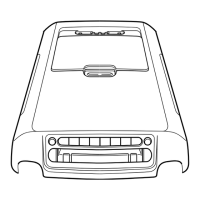
SPINDLE
CALIPER PARTS
2B120 R.H.
2B121 L.H.
2B296
20310-S
34806-S
CALIPER ASS'Y.
2B118 R.H.
2B119 L.H.
INSULATOR
CL.P
2B2
"
2B164
INNER BEARING
CONE AND ROLLER
1201
ANCHOR PLATE
2B293 L.H.
2B292 R.H.
HUB
CUP
CONE AND ROLLER
1216
ROTOR SPLASH SHIE
2K004'R.H.
2K005.LH,
ADJUSTING NUT
374504>S
GREASE CAP
1131
COVER-1130
H 1571-A
FIG. 78—Disc Brake Disassemblied
 Loading...