PART 2-2 - Brake System
2-21
STANDARD
OR
REAR
WHEEL CYLINDER REPAIR
Wheel cylinders should
not be
disas-
sembled unless they
are
leaking
or
unless
new
cups
and
boots
are to be
installed.
It is not
necessary
to
remove
the brake cylinder from
the
backing
plate
to
disassemble, inspect,
or
hone
and overhaul
the
cylinder. Removal
is necessary only when
the
cylinder
is damaged
or
scored beyond repair.
DISASSEMBLY
1.
Remove
the
links
and the
rubber
boots from
the
ends
of the
brake
cyl-
inder. Remove
the
pistons, cups,
and
return spring from
the
cylinder bore
(Fig. 20).
2.
Remove
the
bleeder screw from
the cylinder.
INSPECTION
1.
Wash
all
parts
in
clean brake
fluid.
Dry
with compressed
air.
2.
Replace scored pistons. Always
replace
the
rubber cups
and
dust
boots.
3.
Inspect
the
cylinder bore
for
score marks
or
rust.
If
either condi-
tion
is
present
the
cylinder bore must
be honed. However,
the
cylinder
should
not be
honed more than 0.003
inch beyond
its
original diameter.
4.
Check
the
bleeder hole
to be
sure
that
it is
open.
ASSEMBLY
1.
Apply
a
light coating
of
heavy-
duty brake fluid
to all
internal parts.
2.
Thread
the
bleeder screw into
the cylinder
and
tighten securely.
3.
Insert
the
return spring, cups,
and pistons into their respective
po-
sitions
in the
cylinder bore
(Fig. 20).
Place
a
boot over each
end of the cyl-
inder. Bleed
the
brake system.
WHEEL CYLINDER
REPLACEMENT
REMOVAL
1.
Remove
the
wheel
and
the drum.
2.
Remove
the
brake shoe assem-
blies,
following procedures outlined
in this section.
3.
Disconnect
the
brake line from
the brake cylinder Figs.
19 and
21.
On
a vehicle with
a
vacuum brake boost-
er,
be
sure
the
engine
is
stopped
and
there
is no
vacuum
in the
booster
sys-
tem before disconnecting
the
hydrau-
lic lines.
To disconnect
the
hose
at a
front
cylinder, loosen
the
tube fitting that
BOOT BOOT
CUP
FRONT BRAKE CYLINDER
CUP
BOOT
BOOT
RETURN
SPRING PISTON
CUP
REAR BRAKE CYLINDER
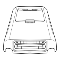
FIG.
20—
Front
and Rear Wheel Cylinders
CUP
H 1100-B
connects
the
opposite
end of the
hose
to
the
brake tube
at a
bracket
on the
frame. Remove
the
horseshoe-type
retaining clip from
the
hose
and
brac-
ket, disengage
the
hose from
the
brac-
ket, then unscrew
the
entire hose
as-
sembly from
the
front wheel cylin-
der.
At
a
rear cylinder, unscrew
the
tube fitting that connects
the
tube
to
the cylinder.
Do not
pull
the
metal
tube away from
the
cylinder. Pulling
the tube
out of the
cylinder connec-
tion will bend
the
metal tube
and
make installation difficult.
The
tube
will separate from
the
cylinder when
the cylinder
is
removed from
the
back-
ing plate.
4.
On the
rear wheel, remove
the
wheel cylinder attaching bolts
and
lock washers
and
remove
the
cylin-
der.
On the
front wheel, remove
the
nut
and
washer that attaches
the cyl-
inder
to the
anchor
pin.
Remove
the
cylinder from
the
anchor
pin.
INSTALLATION
Wipe
the
end(s)
of the
hydraulic
line
to
remove
any
foreign matter
be-
fore making connections.
1.
To
install
a
front wheel cylinder,
position
the
cylinder
on the
anchor
pin against
the
backing plate.
In-
stall
the
washer
and
cylinder attaching
nut
on the
anchor
pin, and
torque
it to
specification. Lock
the
washer retain-
er securely.
2.
Install
a new
copper gasket over
the hose fitting. Thread
the
hose into
the cylinder.
3.
Engage
the
opposite
end of the
hose
to the
bracket
on the
frame.
In-
stall
the
horseshoe-type retaining
clip,
and
connect
the
brake tube
to
the hose with
the
tube fitting
nut.
Tighten
the nut to
specification with
tool 1112-144.
4.
To
install
a
rear wheel cylinder,
place
the
rear wheel cylinder into
position. Enter
the
tubing into
the
cylinder,
and
start
the
tube fitting
nut into
the
threads
of the
cylinder.
5.
Secure
the
cylinder
to the
backing
plate
by
installing
the
attaching bolts
and lock washers.
6. Tighten
the
tube fitting
nut to
specification with tool
11
12-144.
7.
Install
the
links
in the
ends
of
the wheel cylinder, install
the
shoes
and adjuster assemblies,
and
adjust
the shoes
as
oulined
in
this section.
8. Adjust
the
brakes (Part
2-2,
Section
2).
Install
the
brake drum
and
wheel. Bleed
the
brakes
and
central-
ize
the
differential valve
as
outlined
in Part
2-1,
Section
2.
BRAKE BACKING PLATE
REPLACEMENT
REMOVAL
1.
Remove
the
wheel
and
brake
drum. Disconnect
the
brake line from
the brake cylinder.
2.
Remove
the
brake shoe
and ad-
juster assemblies
and the
wheel
cyl-
inder
as
outlined
in
this section.
On
the rear wheels, disconnect
the
park-
ing brake lever from
the
cable.
3.
If the
rear backing plate
is
 Loading...