PART 2-2 - Brake System
2-23
being replaced, remove the axle shaft
from the applicable rear axle as out-
lined in Group 4, Part 4-2—Rear
Axle, Section 2. Remove the backing
plate and gasket.
If the front backing plate is being
replaced, remove the bolts and nuts
that secure the backing plate to the
front wheel spindle and remove the
plate and gasket.
INSTALLATION
If a rear backing plate is to be re-
placed, position a new rear backing
plate and gasket on the attaching
bolts in the axle housing flange. In-
stall the rear axle shaft for the appli-
cable rear axle. Refer to Group 4,
Part 4-2—Rear Axle, Section 2 for the
proper installation procedure.
1.
If the front brake backing plate
is to be replaced, position a new front
backing plate and gasket to the wheel
spindle and install the attaching bolts
and nuts.
2.
Install the wheel cylinder and
connect the brake line as outlined in
this section.
3.
Install the brake shoe and ad-
juster assemblies as outlined in this
section. On a rear brake, connect the
parking brake cable to the lever.
4.
Adjust the brake shoes (Section
2),
and install the brake drums and
wheels. Bleed the brake drums and
wheels. Bleed the brake system and
centralize the differential valve as
outlined in Part
2-1,
Section 2.
HYDRAULIC LINES
Steel tubing is used throughout the
brake system with the exception of
the flexible hoses at the front wheels
and at the rear axle housing brake
tube connection (Figs. 19 and 21).
Always bleed the applicable pri-
mary or secondary brake system after
primary or secondary brake system
hose or line replacement. Centralize
the brake system after bleeding the
system.
BRAKE TUBE
REPLACEMENT
If a section of the brake tubing be-
comes damaged, the entire section
DISC BRAKE
OUTLET TUBE
REAR BRAKES
BUSHING
\ SHAFT (AUTOMATIC
V TRANSMISSION)
I
BLFEDER SCREW
SPACER STUD
CLUTCH
PEDAL
ASSEMBLY
BUSHING
NUT
LOCK WASHER
/
MASTER CYLINDER PUSH ROD
STOP LITE BRAKE PEDAL
SWITCH ASSEMBLY
H 1491-C
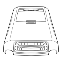
FIG. 22— Master Cylinder Installation— Standard Brakes
should be replaced with tubing of the
same type, size, shape, and length.
Copper tubing should not be used in
a hydraulic system. When bending
brake tubing to fit underbody or rear
axle contours, be careful not to kink
or crack the tube.
All brake tubing should be double
flared properly to provide good leak-
proof connections. Clean the brake
tubing by flushing with clean brake
fluid before installation.
When connecting a tube to a hose,
tube connector, or brake cylinder,
tighten the tube fitting nut to speci-
fied torque with Milbar tool 1112-144
or equivalent.
BRAKE HOSE
REPLACEMENT
A flexible brake hose should be re-
placed if it shows signs of softening,
cracking, or other damage.
When installing a new front brake
hose,
position the hose to avoid con-
tact with other chassis parts. Place a
new copper gasket over the hose fit-
ting and thread the hose assembly in-
to the front wheel cylinder. Engage
the opposite end of the hose to the
bracket on the frame. Install the
horseshoe-type retaining clip, and
connect the tube to the hose with the
tube fitting nut (Figs. 19 and 21).
A rear brake hose should be in-
stalled so that it does not touch the
muffler outlet pipe or shock absorber.
Place a new gasket over the rear
hose fitting and thread the hose into
the rear brake tube connector. En-
gage the front end of the hose to the
bracket on the frame. Install the
horseshoe-type retaining clip, and
connect the tube to the hose with the
tube fitting nut.
REMOVAL AND INSTALLATION
DUAL MASTER CYLINDER-
STANDARD BRAKES
REMOVAL
1.
Working from inside the vehicle
below the instrument panel, disconnect
the master cylinder push rod from the
brake pedal (Fig. 22).
2.
Disconnect the stoplight switch
wires at the connector. Remove the
spring retainer. Slide the stop light
switch off the brake pedal pin just
far enought to clear the end of the pin,
then lift the switch straight upward
from the pin. Use care to avoid switch
 Loading...