1
1-02-0
1
,-
Wheels
11-02-01
-
ART
11-02
Wheels
COMPONENT INDEX
Applies To Models
As Indicated
I
1-1
-
FRONT HUB AND DRUM
I
I
ASSEMBLY
111
Removal and Installation
02-05
1
ASSEMBLY
Removal and Installation
FRONT WHEEL ASSEMBLY
FRONT HUB AND ROTOR
02-05 02-05
Description
I
Removal. Ihstallation. Re~ackine
10243
1
I
02-0 1
ADJUSTMENT
FRONT WHEEL GREASE SEAL
AND BEARING
I
HOISTING INSTRUCTIONS
10242
1
FRONT WHEEL BEARING
0242
'
1
REARWHEEL ASSEMBLY
I
I I
Description
102-01
1
WHEEL AND TIRE (CONVEN-
1
1
I
Removal and Installation
I
102-031
I
I I I
I
A page number indicates that the item is for the vehicle(s)
isted at the head of the column.
I
N/A indicates that the item is not applicable to the ;ehicle(s) listed.
1
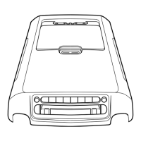
DESCRIPTION
FRONT WHEEL ASSEMBLY
Each front wheel and tire is bolted
to its respective front hub and brake
drum or rotor assembly. Two op-
posed tapered roller bearings are in-
'
stalled ii each hub.
A
retainer
is installed at the inner end of the hub
to prevent lubricant from leaking into
the drum or on the rotor. The entire
assembly is retained to its
spihdle by
the adjusting nut, nut lock and cotter
pin (Figs.
I
and
2).
r.
REAR WHEEL ASSEMBLY
The rear wheel hub and brake
drum assembly is attached to studs on
the rear axle shaft flange by three
speed nuts. The wheel and tire
mounts on the same rear axle shaft
flange studs and is held against the
hub and drum by the wheel nuts. The
rear wheel bearing is pressed onto the
axle shaft just inside the shaft flange,
and the entire assembly is retained to
the rear axle housing by the bearing
retainer plate which is bolted to the
housing flange.
FIG.
I-Front Hub, Bearing and Grease Retainer Drum Brakes
 Loading...