8 9
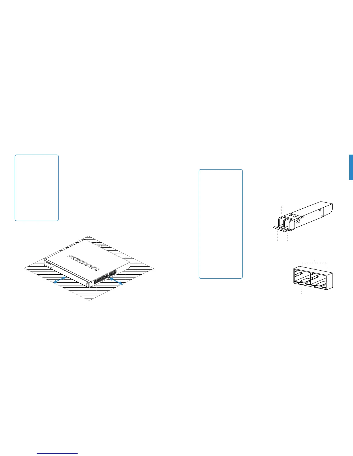
7RLQVWDOOWKHXQLWRQDÁDWVXUIDFH
1. Ensure that the surface onto which the FortiGate unit
to be installed is clean, level, and stable and that
there is at least 1.5 inches (3.8cm) of clearance on all
TJEFTUPBMMPXGPSBEFRVBUFBJSnPX
2. Attach the provided rubber feet to the bottom of the
FortiGate unit.
3. Place the unit in the designated location.
4. Verify that the spacing around the FortiGate unit
conforms to requirements and that the unit is level.
5. Using the provided power cable, plug the cable
into the rear of the unit, and then into a grounded
electrical outlet or separate power source.
Note: If the unit
has a redundant
power supply, each
power cable should
be connected to
a different power
source. In this way,
if one power source
fails, the other may
still be operational
and the unit will not
lose power.
1.5in
1.5in
Caution: SFP
transceivers are static
sensitive devices. Use
an ESD wrist strap
or similar grounding
device when handling
transceivers.
Do not install
or remove SFP
transceivers while
mCFSPQUJDDBCMFTBSF
still attached. This
can cause damage
to the cables, cable
connectors, and the
optical interfaces.
It may also prevent
the transceiver from
latching correctly into
the socket connector.
SFP Transceivers
Transmit Optical Bore
Receive Optical Bore
SFP Cage Sockets
Socket Latch
To install the SFP transceivers
1. Ensure that you are properly grounded.
2. Remove the caps from the SFP cage sockets on the
front panel of the unit.
Extraction Lever
 Loading...