This document is a user guide for the FORTIS Magnetic Flywheel Spin Bike, model SK-600 (FSMFWSPNBKA).
Function Description
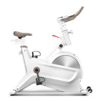
The FORTIS Magnetic Flywheel Spin Bike is a fitness device designed for indoor cycling workouts. It features a magnetic flywheel system for resistance, allowing users to adjust the intensity of their exercise. The bike includes a display that tracks various workout metrics, such as time, speed, distance, calories, and pulse rate. The handlebars and seat are adjustable to accommodate different user heights and preferences, ensuring a comfortable and effective workout. Pedals are equipped with straps for secure foot placement. The bike is also designed for easy transport within a home or gym setting.
Important Technical Specifications
The user guide provides a detailed overview of the bike's components and their dimensions. Key components include:
- Main Frame (81): The primary structural component of the bike.
- Flywheel (72) and Flywheel Axle (73): Central to the magnetic resistance system.
- Magnetic Plate (58) and Magnets (56): These components, along with the magnetic locator (57), create the magnetic resistance.
- Tension Knob (52) and Tension Knob Bracket (92): Used to adjust the resistance level.
- Handlebar (78) and Handlebar Post (74): Adjustable for user comfort.
- Seat (29) and Seat Post (31): Adjustable vertically and horizontally.
- Pedals (90L/R): Designed for secure foot placement during exercise.
- Display (87): Shows workout metrics and requires two batteries (96) with a battery cover (95).
- Stabilisers (Front 1, Rear 12): Provide stability to the bike.
- Crank (39L/R): Connects the pedals to the flywheel system.
- Belt (51): Drives the flywheel.
- Brake Pad (62) and Braking Vane (63): Components of the braking system.
- Inductor (89) and Trunk Line (88): Electrical connections for the display.
- Foot Pads (3): Adjustable for balancing the bike.
Dimensions of specific parts (in mm):
- Front stabiliser (1): Dimensions not specified, but uses M8x20xS6 screws (9), d8 spring washers (10), and d8xΦ16x1.5 washers (11).
- Rear stabiliser (12): Dimensions not specified, but uses M8x20xS6 screws (9), d8 spring washers (10), and d8xΦ16x1.5 washers (11).
- Foot pad (3): Φ43 x 14 x M8 x 25.
- End cap PT70 x 30 x 20 (4).
- Screw M6 x 12 x S5 (5).
- Bearing 608ZZ (6).
- Transport wheel (7): Φ71 x Φ19 x 24.
- Screw (8): Φ7.8 x 30 x M6 x 15 x S5.
- Screw (9): M8 x 20 x S6.
- Spring washer (10): d8.
- Washer (11): d8 x Φ16 x 1.5.
- Knob (13): M16 x 1.5 x 27 x Φ56.
- Bushing (14): PT80 x 40 x PT70 x 30 x L130.
- Brake block (15): 68 x 75 x 39.2.
- Screw (16): M5 x 7 x Φ10.
- Brake cable (17): Φ1.5 x 255 x 42.
- Bolt (18): M6 x 10 x H26 x S5.
- Brake handle (19).
- Washer (20): Φ8.5 x Φ23.5 x 3.
- Spring (21): Φ1.2 x Φ11 x 21 x N7.
- Cable base (22): T3 x 25 x 23.
- Nylon nut (23): M6 x H6 x S10.
- Hexagon bolt (24): M6 x 10 x S10.
- Washer (25): 6 x Φ16 x 1.5.
- Bearing (26): 6001-2RS.
- Idle pulley (27): Φ39 x Φ34 x 24.
- Wave washer (28): d12 x Φ15.5 x 0.3.
- Seat (29).
- Seat slider (30).
- Seat post (31).
- End cap (32): PT50 x 25 x 16.
- Washer (33): d10 x Φ30 x 2.5.
- Knob (34): M10 x Φ58 x 32.
- Cover (35): 99.3 x 83.5 x 24.7.
- Bushing (36): PT70 x 30 x PT60 x 20 x L145 x 10.
- Crank plug (37): Φ25x7.
- Hexagon nut (38): M10 x 1.25 x H7.5 x S14.
- Crank (39): Left and Right.
- Crank ring (40): Φ83 x Φ31 x 14.
- Screw (41): ST4.2 x 16 x Φ8.
- Screw (42): ST4.2 x 19 x Φ8.
- Housing (43).
- RING-SHIELD (44): d17.
- Bearing (45): 6203-2RS.
- Bushing (46): Φ22 x Φ17.2 x 5.5.
- Magnet (47): Φ15x7.
- Belt plate (48): Φ220 x 20 x Φ17.1 x 4-Φ6 x Φ60-6PJ.
- Shaft (49): Φ17 x 188 x 59.5 x 78 x 4-Φ6.1 x Φ60.
- Bolt (50): M6 x 16 x S10.
- Belt (51).
- Tension knob (52).
- Spring washer (53): d6.
- Washer (54): d6 x Φ12 x 1.2.
- Ring-shield (55): d12.
- Magnet (56): 40 x 25 x 10.
- Magnet locator (57): 45.5 x 130 x 10.5.
- Magnetic plate (58).
- Magnetic plate shaft (59): Φ12 x 53.5 x 47.4 x M6.
- Screw (60): ST3 x 10 x Φ5.6.
- Spring (61): Φ1.5 x Φ15 x 54 x N9.
- Brake pad (62): 60 x 27 x 5.
- Braking vane (63).
- Screw (64): M6 x 16 x S5.
- Brake connected plate (65).
- Hexagon nut (66): M12 x 1 x H11 x S18.
- Hexagon nut (67): M10*1.0.
- Bolt (68): M6 x 50 x Φ12 x 4.
- U-bracket (69).
- Hexagon nut (70): M12 x 1 x H7 x S19.
- N/A (71).
- Flywheel (72).
- Flywheel axle (73).
- Handlebar post (74).
- Screw (75): M5 x 8 x Φ10.
- Screw (76): M8 x 16 x S6.
- Nut (77): M12 x 1 x H5 x S19.
- Handlebar (78).
- End cap (79): Φ25x16.
- Foam Grip (80): Φ23 x 3 x 420.
- Main frame (81).
- Washer (82): d5 x Φ13 x 1.
- Screw (83): M5 x 16 x Φ8.
- Heart rate slice (84).
- Screw (85): ST4.0 x 19 x Φ11.
- Plug (86): Φ12 x 11 x Φ3.
- Display (87).
- Trunk line (88).
- Inductor (89).
- Pedal (90): Left and Right.
- PU Washer (91).
- Tension knob bracket (92).
- Wave washer (93): d17 x Φ22 x 0.3.
- Washer (94): d5 x Φ10 x 1.0.
- Battery cover (95).
- Battery (96).
- Idler Shaft (97).
- Nylon nut (98): 9/16" L and 9/16" R.
- Allen wrench (A): S6.
- Spanner (B): S13 - S15.
- Spanner (C): S17 - S19.
Usage Features
The spin bike offers several features to enhance the user experience:
Assembly:
- Stabiliser Attachment: The front and rear stabilisers are attached to the main frame using screws, spring washers, and washers.
- Pedal Installation: The pedals (90L/R) are screwed into the cranks (39L/R) and secured with a spanner (B), then tightened with nylon nuts (98L/R) using spanner (C).
- Handlebar Assembly: The trunk line (88) is passed through the handlebar post (74), which is then attached to the handlebar (78) and secured with screws (76), spring washers (10), and washers (11). The handlebar post (74) and trunk line (88) are inserted into the main frame (81) and secured with the knob (13). The trunk line (88) is connected to the inductor (89).
- Display Battery Installation: Two batteries (96) are inserted into the display (87) after removing the battery cover (95), ensuring correct polarity. The battery cover is then replaced.
Operation:
- Mode/Reset Button: Pressing cycles through display operations. Holding for 3 seconds resets time, distance, and calories.
- Display Functions (SCAN): Automatically rotates through Time (TMR), Speed (SPD), Distance (DST), Calories (CAL), and Pulse Rate (PULSE), each displayed for 6 seconds.
- Pulse Rate Measurement: Place both palms on contact pads for 3-4 seconds to display heart rate in BPM. Note: Initial readings may be higher than actual heart rate. This feature is not for medical treatment.
- Auto-Off: The display turns off automatically after 4 minutes of inactivity. It can be reactivated by moving the wheel or pressing any button.
Adjustments:
- Balance: The foot pads (3) can be turned counter-clockwise to adjust the bike's balance.
- Handlebars:
- Rotate the Handlebar Adjustment Knob counter-clockwise and pull it out.
- Adjust the handlebar post (74) up or down to the desired height.
- Rotate the knob clockwise to secure the handlebar post, aligning it with the handlebar post hole.
- Seat:
- Vertical Adjustment: Rotate the Seat Adjustment Knob (1) counter-clockwise and pull it out. Adjust the seat post (31) vertically.
- Horizontal Adjustment: Rotate the Seat Slider Adjustment Knob (2) counter-clockwise and pull it out. Adjust the seat (29) horizontally.
- Tighten the respective knobs clockwise to secure the seat in position, aligning with the seat post hole.
- Resistance and Braking:
- Resistance Adjustment: Rotate the Tension Adjustment Knob to increase or decrease resistance.
- Emergency Braking: Depress the emergency brake handle to stop the bike immediately.
- Pedal Straps: Press the buckle and pull the strap up to loosen, or pull down to tighten.
Transporting:
- Ensure the handlebar is secured.
- Stand in front of the handlebars.
- Grasp both sides of the handlebar, place one foot on the front stabiliser, and tilt the bike towards you until the transport wheels touch the ground, allowing for easy movement.
Maintenance Features
The user guide includes safety warnings that imply certain maintenance aspects:
- Lubrication: It is recommended to lubricate all moving parts every month.
- Cleaning: After each use, wipe down the bike to remove moisture. Use a mild, non-abrasive cleaner and water solution. Avoid petroleum-based solvents.
- Inspection: Regularly inspect the seat post, seat slider, pedals, and handlebar to ensure they are in a safe and stable position.
- Hardware Check: Periodically inspect and ensure all hardware parts (bolts, nuts, washers) are positioned correctly and tightened securely.
- Chain Guard: Ensure the safety chain guard protects moving parts.
- Footwear: Do not remove footwear from the pedals while they are in motion. Wear running shoes or other footwear suitable for exercise.
The manual also provides general safety warnings, such as reading instructions, ensuring proper assembly, not wearing loose clothing, keeping children away from the bike, and consulting a physician before starting an exercise program, especially if experiencing pain or discomfort. It also specifies operating and storage temperature ranges for the device.