43
Fortress S-Series
18.2 WHEEL REMOVAL
WARNING!
• It is not usually practical to try to repair a puncture
in situ at the site of the occurrence. Sunrise Medical
suggests that you call for help to remove the scooter
either directly to an approved service agent, or to a
safe place for collection by the approved agent at a
later time.
• If you are in any doubt about the servicing
requirements of your scooter contact your Sunrise
Medical authorized dealer.
• Do not attempt any task you are not sure of.
• Do not attempt a puncture repair if the scooter has
stopped in an unsafe area. Move the scooter to a
safe area away from traffic and other hazards.
• Do not attempt a puncture repair in busy pedestrian
areas.
• Do not attempt a puncture repair if the scooter is
causing an obstruction.
• If you are using a jack or other equipment, always
follow the user instructions given in the related
Owners’ Manual or User Instructions.
• Be aware that the scooter may fall off the jack at any
time.
• Keep hands and feet clear of the scooter when it is
on the jack.
• Do not stand the jack on uneven surfaces.
• Always use a support block or stand in conjunction
with the jack.
• The scooter must be in drive mode with the power
switched OFF and the keys removed, before jacking
any wheel off the ground.
• Do not raise more than one wheel off the ground at
any one time.
NOTE: Reverse the following procedures to refit the
wheels unless otherwise stated.
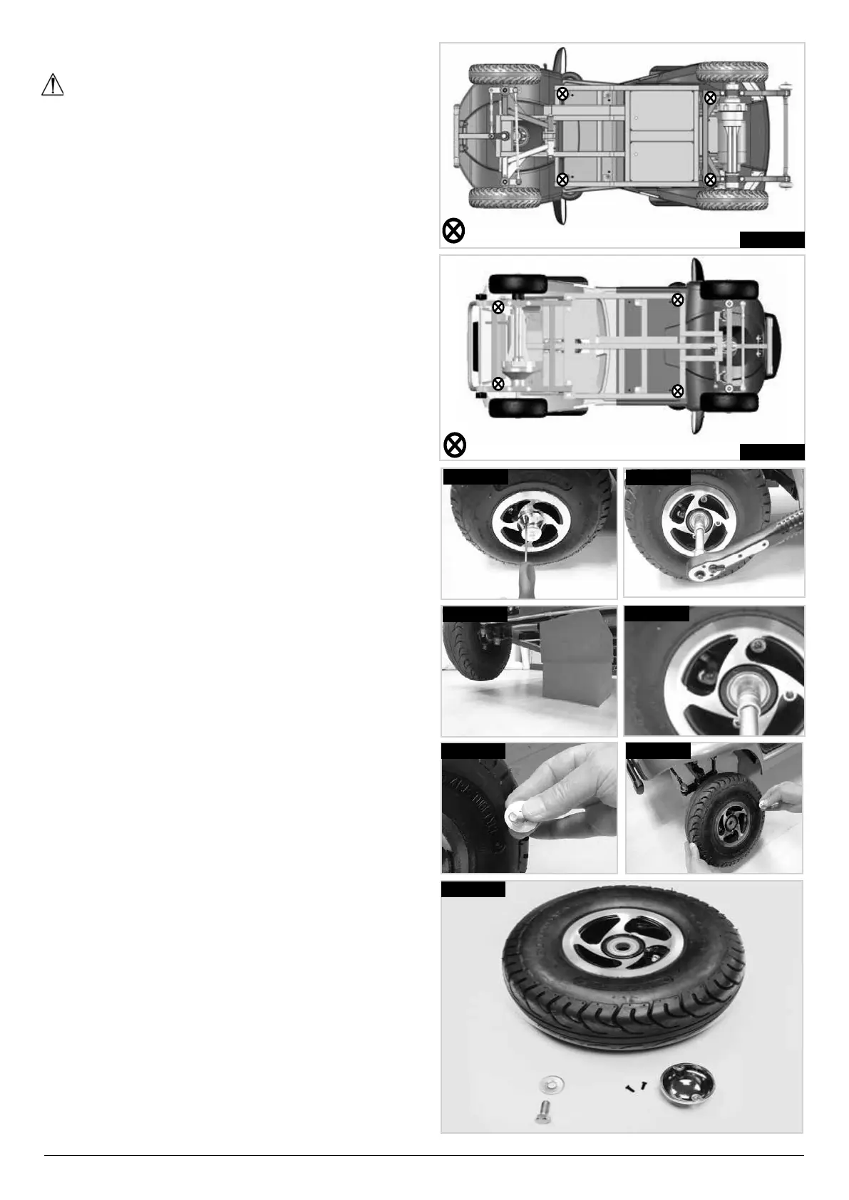
18.2.1 S-SERIES FRONT WHEEL REMOVAL
• Use a small Phillips screw driver to undo the two
screws securing the hub cover and remove it,
(FIG.18.2)
• Use a 6 mm Allen key/driver to loosen the nut, but do
not remove it yet, (FIG.18.3).
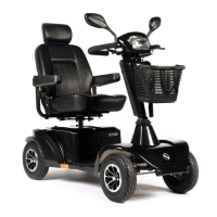
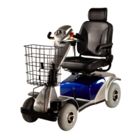
• Elevate the front wheel by placing a jack under the
relevant jack points, (FIG.18.1-18.1.1),
• When elevated, back up the jack with solid blocks to
increase stability, (FIG.18.4).
• Use a 6 mm Allen key/driver or your fingers to
remove the nut, (FIG.18.5).
• Do not lose the washers, (FIG.18.6).
• Withdraw the wheel off the tapered shaft, (FIG.18.7).
• The front wheel assembly is shown in FIG.18.8.
= JACK/BLOCKING POINTS S425
FIG.18.1.1
FIG.18.2
FIG.18.3
FIG.18.4
FIG.18.5
FIG.18.6
FIG.18.7
FIG.18.8
= JACK/BLOCKING POINTS S700
FIG.18.1
 Loading...