Edition 2003 B0310003 7
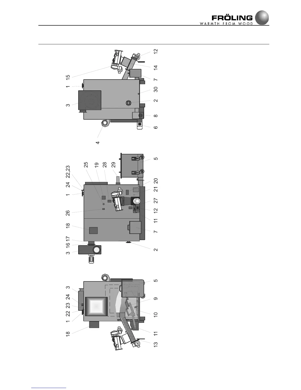
Assembly
1 .....Outfeed
2 .....Return feed
3 .....Induced draught fan
4 .....Combustion air blower fan
5 .....Ash trolley
6 .....Ash screw drive
7 .....Ash can
8 .....Ash can screw drive
9 .....Conveyor grate
10 ...Ash rake
11...Grate and rake drive
12...Stoker screw drive
13... Stoker screw
14... Blow-back flap
15... Feed screw drive
16...Lambda probe (3/4” connector)
17...Flue gas sensor (1/2” connector)
18... Heat exchanger drive
19... STB housing
20... Undepressure measuring port
21....Underpressure measuring connector
22....Boiler sensor, STB sensor
23....Safety battery sensor
24....Safety battery connections
25....Combustion chamber temperature sensor
26....RGTW (combustion chamber overpressure)
27....Primary air setting motor
28....Secondary air setting motor
29 ...Igniter
30....Cleaning port
 Loading...