9
EN-US
Choosing the Location
Intended Use The inverter is designed exclusively to be connected and used with nongrounded solar
modules. The solar modules cannot be grounded at either the positive or negative pole.
The solar inverter is designed exclusively to convert direct current from solar modules into
alternating current and feed this power into the public grid.
The following are deemed not to be in conformity with its intended purpose:
- utilization for any other purpose, or in any other manner
- alterations to the inverter that are not expressly recommended by Fronius
- installation of components that are not expressly recommended or sold by Fronius.
The manufacturer is not responsible for any damage resulting from improper use.
All warranty claims are considered void in such cases.
Proper use also means
- carefully reading and obeying all the instructions and safety and danger notices in the
operating instructions
- carrying out all the specified inspection and servicing work
- installation as per operating instructions.
When configuring the photovoltaic system, make sure that all photovoltaic system compo-
nents are operating completely within their permitted operating range.
All measures recommended by the solar module manufacturer for maintaining solar mod-
ule properties must be followed.
Utility company regulations regarding grid power feed must be followed.
Selecting a Loca-
tion – General In-
formation for
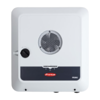
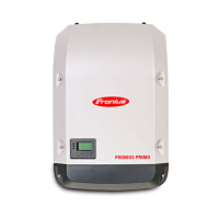
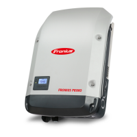
Fronius Primo
3.8–8.2
Please note the following criteria when choosing a location for the inverter:
Only install on a solid surface
Max. ambient temperatures:
-40°F to +131°F
(-40°C to +55°C)
Relative humidity:
0–100%
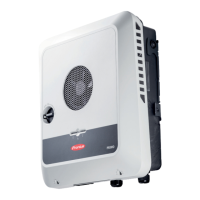
The air flow direction within the
inverter is from left and right to
top (cold air intake on the left and
right, hot air outflow at the top).
The waste air can reach a tem-
perature of 70°C.
When installing the inverter in a switch cabinet or similar closed environment, it is neces-
sary to make sure that the hot air that develops will be dissipated by forced-air ventilation.
If you wish to install the inverter on the outer walls of a cattle shed, it is important to main-
tain a minimum clearance of 6 ft. 7 in. (2 m) between all sides of the inverter and air vents
and other openings.
The place of installation should not be exposed to ammonia, corrosive gases, salts, or ac-
ids.
8 in.
200 mm
4 in.
100 mm
6 in.
150 mm
-40 °F - +131 °F
-40 °C - +55 °C
0 - 100 %
 Loading...
