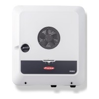
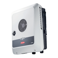
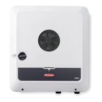
Installation location and position
Choosing the
location of the
inverter
NOTE!
Risk from unsuitable choice of location for the inverter.
Failure or restricted operation of the inverter may result.
▶
Adhere to the instructions relating to the location, according to this chapter
▶
Adhere to national provisions and guidelines when installing the inverter.
Please note the following criteria when choosing a location for the inverter:
Only install on a solid, non-flam-
mable surface.
Max. ambient temperatures:
-40 °F - +140 °F / -40 °C - 60 °C
Relative humidity:
0 - 100%
When installing the inverter in a
switch cabinet or similar closed en-
vironment, it is necessary to make
sure that the hot air that develops
will be dissipated by forced-air vent-
ilation.
For more detailed information on in-
verter dimensions, refer to the
chapter headed Fronius Primo
GEN24 7.7 - 10.0 208-240 on page
119.
When installing the inverter on the outer walls of cattle sheds, it is important
to maintain a minimum clearance of 6.5 ft between all sides of the inverter and
the ventilation and building openings.
The following substrates are permissible for installation:
-
Walls ( non-flammable surfaces sufficiently capable of bearing loads):
-
Corrugated metal walls [mounting rails]
-
Brick walls
-
Concrete walls
-
Vinyl siding walls
-
Wood siding walls
-
Stucco wall
-
Poles (installed using mounting rails, behind the PV modules directly on
the PV mounting system)
-
Covered parking lot roofs (no overhead installation)
The inverter is suitable for indoor installation.
37
 Loading...

