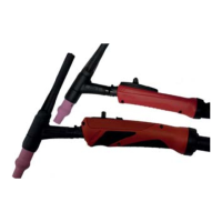
(3)
(2)
ABCDEF
SH
Brown
Grey
White
Pink
Green
Yellow
(3)
(2)
U/D
NOTE!
Observe the pin assignment
*
(color-
coded arrangement of the wires) for
each interface version and note it down
in advance.
3
Release the wires (2) using tweezers
and pull them out
4
Replace the socket housing (3)
5
Insert the wire cords (2) into the
socket housing (3) according to the
color arrangement
*
per interface ver-
sion and check the lock
6
Connect the user interface PCB (1)
7
Position the user interface PCB (1)
and coupling housing (4) in the handle
8
Apply the HF insulation (5)
9
Close the hand grip as per the “Clos-
ing the hand grip” chapter
40

 Loading...


