68
3
Selection and application
3-7 Welder circuit applications
However, since the standard maximum input is prescribed
for a resistance welder, even if the secondary circuit is fully
shorted, the maximum short-circuit current is some 30%
higher than the rated welding current (secondary current
corresponding to the standard maximum input) at most.
Consequently, allowance would be needed only for a value
about 30% higher than the current corresponding to the
standard maximum input.
Assuming a standard maximum input of 55kVA at 230V AC
single-phase, I
L (max) is calculated as
u 1.3 | 310 [A]
55000
230
I
L (max) =
This result requires that the tL−IL curve shown in Fig. 3-24
be positioned below the hot-start characteristic curve of the
MCCB in the range I
L d 310 (A). A general guideline for filling
this requirement is to set the rated current of the MCCB at
least 1.5 times higher than the thermal equivalent current
calculated in (i).
(iii) Method to keep the MCCB free from malfunctioning
caused by the inrush current when the circuit is
closed.
With welders that use thyristors to permit closed circuit phase
control, such as those operating in synchronous or semi-
synchronous mode, the inrush current associated with the
biased excitation of the transformer core would not be much
of a problem. Rather, only the inrush current associated with
the superposed DC component needs to be considered.
Specifically, a choice should be made of an MCCB having its
instantaneous tripping current at least two times the I
L (max)
calculated in (ii).
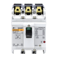
Table 3-19 lists typical MCCBs that are selected to work with
resistance welders that operate in synchronous or semi-
synchronous mode, pursuant to the requirements given in (i)
to (iii) above. Since, generally, the standard maximum input
of a welder is some three times its rated capacity, and the
instantaneous tripping current of an MCCB is eight times
its rated current or higher, the following equation may be
used to select an MCCB to work with welders that operate in
synchronous or semi-synchronous mode:
IN > 1.1 u
Rated capacity
Rated voltage
Assumption:
Max. input capacity
Rated capacity
d 3
I
N = MCCB rated current
Table 3-19 Spot welder circuit motor breaker selection
Note: This table applies to models that can use a thyristor to perform phase
control at startup for a synchronous or semi-synchronous system.
Resistance welder Single-phase, 200V
Circuit short-circuit capacity (kA) (The
short-circuit current at the service entrance
must be less than the following values.)
Rated
capacity
example
(kVA)
Maximu
m input
example
(kVA)
5 253650100
15 35 BW100
AAG-
2P100
BW100
EAG-
2P100
BW125JAG-
2P100
30 65 BW125JAG-2P125 BW125
RAG-
2P125
55 140 BW250EAG-2P225 BW250RAG-
2P225
Resistance welder Single-phase, 400V
Circuit short-circuit capacity (kA)
(The short-circuit current at the
service entrance must be less
than the following values.)
Rated
capacity
example
(kVA)
Maximu
m input
example
(kVA)
10 18 30 50
15 35 BW50
RAG-
2P050
BW125JAG-
2P050
BW125
RAG-
2P050
30 65 BW100
EAG-
2P100
BW125JAG-
2P100
BW125
RAG-
2P100
55 140 BW250EAG-2P225 BW125
RAG-
2P125

 Loading...


