82
3
Selection and application
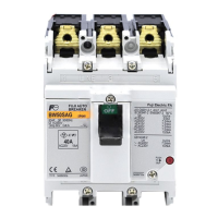
3-13 MCCBs for DC circuit applications
Table 3-27 Disconnect switches line up
Rated voltage Frame size
32 50 63 100 125 250 400 630 800
DC 250V BW32SAS BW50SAS BW63SAS BW100EAS BW125JAS BW250EAS BW400EAS BW630EAS BW800EAS
BW125RAS BW250RAS BW630RAS
400V BW32SAS-
3P C4
BW50SAS
-3P C4
BW63SAS
-3P C4
BW100EAS
-3P C4
500V
①
BW125JAS
-3P C5
BW250EAS
-3P C5
BW400EAS
-3P
BW630EAS
-3P
BW800EAS
-3P
BW125RAS
-3P C5
BW250RAS
-3P C5
BW400RAS
-3P
BW630RAS
-3P
BW800RAS
-3P
600V
①
BW125RAS
-4P C6
BW250RAS
-4P C6
BW400RAS
-4P
BW630RAS
-4P
BW800RAS
-4P
650V BW50SAS
-3P 0A0
□
5
700V
750V BW400RAS
-3P CP
BW630RAS
-3P CP
BW800RAS
-3P CP
800V
1000V BW400RAS
-4P CP
BW630RAS
-4P CP
BW800RAS
-4P CP
Note 1) While 400 - 800AF can be used for the standard products of DC500V(3-pole item) and DC600V(4-pole item), only DC250V is cited on the nameplate. If it is necessary to indicate
DC500V or DC600V, please specify “C5” or “C6” at the end of the type description.
3P(250V)
Load
−(N)
+(P)
Load
4P (251 to 1000V DC)
−(N)+(P)
2P (250 V)
Load
−(N)
+(P)
Load
3P (251 to 750V DC)
−(N)
+(P)
Example of wiring diagram
In the circuit exceeding DC250V, it is necessary to ensure the
switching performance and breaking performance by conduct-
ing serial connection of contacts for 3-pole or 4-pole items.
Note: The connection method may change depending on the
type.
Please confirm the details on the pages listing the characteris-
tics and external form of each product.

 Loading...


