58
3
Selection and application
3-5 Motor circuit applications
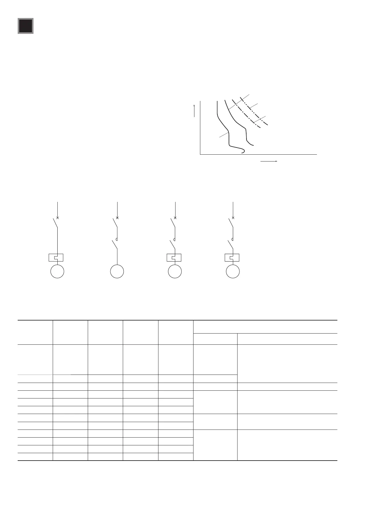
Fig. 3-17 Protective structure for motor circuits
M
Motor protection
MMS
Motor protection
MCCB or MMS
M
Contactor
Starter
Starter
MM
Line protection
MCCB
ba
c
d
Instantaneous trip type MCCB
Table 3-12 Selection of manual motor starters (MMS)
(a) 230V AC
Combined
magnetic
contactor
Motor output
(kW)
Motor rated
current (A)
Motor rated
current
multiplying
factor (A)u1.2
Manual motor
starter rated
current (A)
Manual motor starter
Icu (kA)
50 100
SC-03 0.2
0.4
0.75
1.5
2.2
0.96
1.65
2.87
5.2
7.0
1.15
1.98
3.45
6.3
8.4
1.2
2.3
3.5
7
9
–
BM3RSB-
BM3RHB-
BM3VSB-
BM3VHB-
SC-4-0 3.7 11.7 14.1 14
BM3RSB-
SC-N1 5.5 17.4 20.9 21
BM3VSB- BM3RHB-
SC-N2 7.5 23.1 27.7 28
BM3VSB- BM3VHB-
BM3VHB-
SC-N2S 11 33.9 40.7 40
SC-N3 15 45.2 54.3 52
SC-N4 18.5 54.8 65.8 65 – –
SC-N5, N5A 22 67 80.4 80
SC-N6 30 89.6 107.5 110 – –
SC-N7 37 110.5 132.6 130
SC-N8 45 132.2 158.7 150
SC-N10 55 163.6 196.3 200
Note: Motor full-load currents are based on FUJI’s standard type totally-enclosed
induction motors. Check the value of the full-load current before using.
Fig. 3-16 Motor breaker protection coordination
Motor breaker characteristics
Time
Current
Motor allowable characteristics
Cable allowable characteristics
Motor current
(2) Motor circuit protection by motor breaker
The overcurrent trip characteristics of a single MCCB may
be used to protect the motor and the wiring at the same time.
(See Fig. 3-17 a.)
Often the operating characteristics of an MCCB make it
unsuitable in situations with long starting times or with
significant current, like the inrush current generated by the
changeover from star to delta connection. However, MCCBs
are quite suitable for short (2s or less) starting times.
The need for frequent switching brings up other important
considerations, such as connecting magnetic contractors in
series. (See Fig. 3-17 b.) Fig. 3-16 shows the MCCB protection
coordination curve. Table 3-12 (a) shows applicable breakers
for 230V motors and Table 3-12 (b) shows breakers for 400V
motors.
 Loading...