60
3
Selection and application
3-5 Motor circuit applications
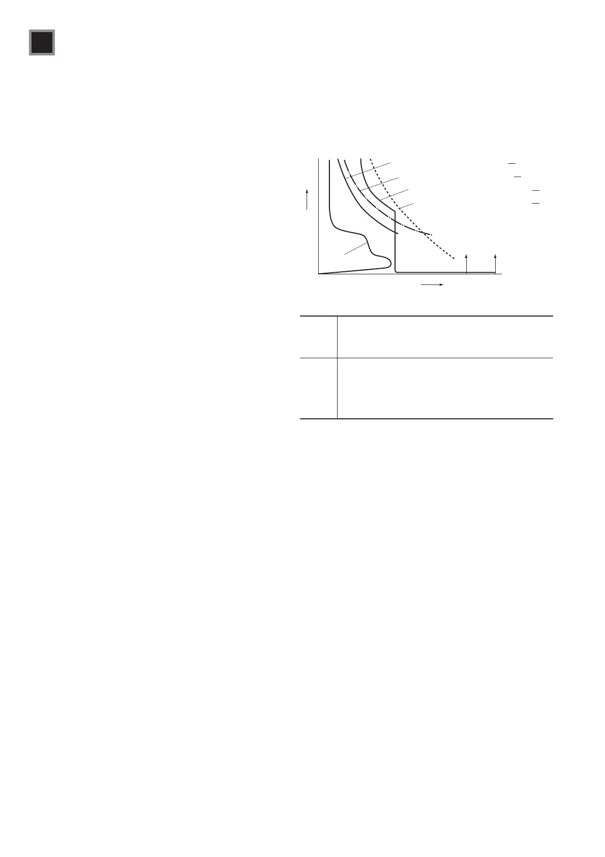
Fig. 3-18 Protection coordination characteristics curve in motor
circuits
Motor current
TOR's operating characteristics
Available
short-circuit
current
Current
Time
Motor allowable characteristics
MCCB's operating characteristics
Cable allowable characteristics
1
2
3
4
Rated short-
circuit breaking
capacity (Icu)
Table 3-13 Magnetic motor starter protection class (IEC 60947-4-1)
Type 1 Coordination requires that, under short-circuit conditions,
the contactor or starter shall cause no danger to persons
or installation and may not be suitable for further service
without repair and replacement of parts.
Type 2 Coordination requires that, under short-circuit conditions,
the contactor or starter shall cause no danger to persons
or installation and shall be suitable for further use. The
risk of contact welding is recognized, in which case the
manufacturer shall indicate the measures to be taken as
regards the maintenance of the equipment.
(3) Magnetic motor starter and MCCB motor circuit
protection
These arrangements consist of a magnetic motor starter
and line protection or instantaneous trip type of MCCB. The
starter’s thermal overload relay operates in the presence of
sustained overload currents. The MCCB interrupts short-circuit
currents. This is the most popular method.
For control centers where short-circuit currents are large,
instantaneous trip type MCCBs are used. This is because
standard MCCBs for line protection are provided with bimetal
elements as tripping devices, which have limited overcurrent
withstand values and which would cause damage due to
overheating in the presence of short-circuit currents.
Fig. 3-18 gives an example of a protection coordination curve
of a motor circuit.
When combining the MCCB with a magnetic motor starter, the
fundamental rules for protection are as follows:
s 4HECOMBINEDPROTECTIONCHARACTERISTICSOFANDMUST
operate before the motor and wire sustain damage.
s 4HE-##"DOESNOTTRIPFROMSTARTINGCURRENTORFROM
current while the motor is running at the rated load.
s 4HE-##"MUSTBEABLETOINTERRUPTSHORTCIRCUITCURRENTS
s )NANOVERLOADCONDITIONTHESTARTEROPERATESBEFORETHE
MCCB.
s 4HE-##"OPERATESWHENMORECURRENTmOWSTHANTHE
starter can interrupt. This protects the starter.
Even though the above requirements are satisfied and the
MCCB interrupts, the heating element of the thermal overload
relay can be damaged due to overheating caused by the
magnetic force or the energy of the short-circuit currents.
This means that it is impossible for the MCCB to provide
absolute protection for motor starters when short-circuit faults
occur. It is therefore not realistic or economical to protect
magnetic motor starters by means of MCCBs.
Therefore, magnetic motor starter protection is divided into two
types by IEC 60947-4-1, with the prior understanding that the
motor starter must be replaced or repaired after a short-circuit
fault has occurred. Refer to Table 3-13.
 Loading...