FUNCTION CODES
Chap 5
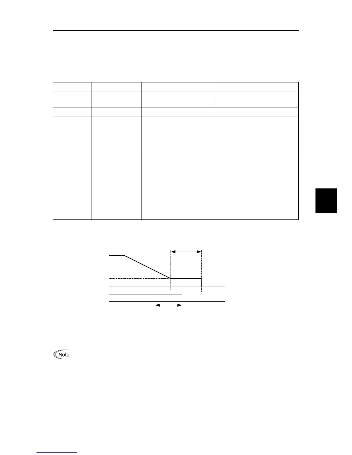
Applying the brake
When the run command is OFF and the output frequency drops below the level specified by J71 (Brake control
signal (Brake-applied frequency/speed)) and stays below the level for the period specified by J72 (Brake control
signal (Brake-applied timer)), the inverter judges that the motor rotation is below a certain level and turns the signal
“BRKS” OFF for activating (applying) the brake.
This operation reduces the load applied to the brake, extending lifetime of the brake.
Function code Name Data setting range Remarks
J71 Brake-apply
frequency/speed
0.0 to 25.0 Hz
J72 Brake-apply timer 0.00 to 5.00s
J96 Brake-apply
conditions (Only
available when
using vector control
with speed sensor)
0 to 31 (in decimal)
Criteria of speed condition for
Brake-apply (Bit 0)
0: Detected speed (default)
1: Reference speed
Specifies the criteria of speed to be
used for Brake-apply condition.
Condition of brake-apply
control signal (Bit 4)
0: Regardless of run
command status (ON or
OFF) (default)
1: Only when run command is
OFF.”
Specifies whether to turn off a brake
control signal independent of a run
command ON/OFF or only when a
run command is OFF.
When forward and reverse
operations are switched,
Brake-applied conditions may be
met in the vicinity of zero speed. For
such a case, select “Only when a
run command is OFF” (Bit 4 = 1).
Note: Resolution of each function code is different from the FRENIC-MEGA and FRENIC-Multi.
Figure 5.3-15 Time chart

 Loading...


