Page 7 of 28 Fuji Electric Europe GmbH
3. Technical data
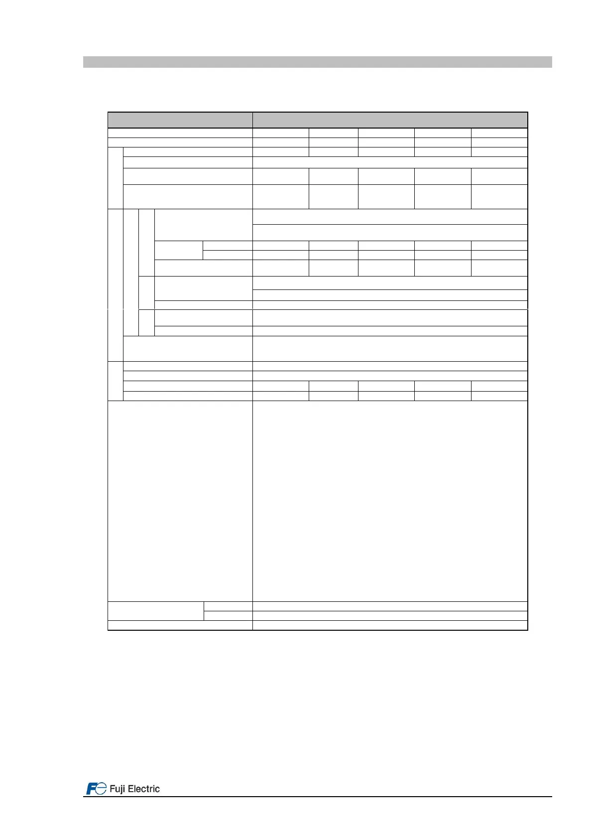
3.1 Specifications
Table 3.1. FRENIC-Lift LM2C General specifications.
Nominal applied motor [kW]
Overload capacity [A]
(Permissible overload time)
Phases, voltage, frequency
3-ph 380 to 480 VAC, 50/60 Hz
Variations: Voltage: +10 to -15% (Voltage unbalance: 2% or less
4
), Frequency: +5 to -
5%
Required power supply
capacity (with DCR) [kVA]
Input power for driving
phases, voltage, frequency
1-ph 220 to 480 VAC, 50/60 Hz
Variations: Voltage: +10 to -10%, Frequency: +5 to -5%
Input power for driving
voltage
Aux. control power voltage
24 VDC (22 to 32 VDC), max. 40 W
Braking duty-cycle (%ED)
7
[%]
Rated regenerative power
7
[kW]
Lift Directive
- Replacement of two motor contactors: interrupting the current to the motor (to stop
the machine), as required by EN 81-20:2014 5.9.2.5.4 d & 5.9.3.4.2 d
Machinery Directive
- EN ISO13849-1: PL-e
- EN60204-1: stop category 0
- EN61800-5-2: STO SIL3
- EN62061: SIL3
Low Voltage Directive
- EN61800-5-1: Over voltage category 3
EMC Directive
- with external EMC filter EN12015, EN12016, EN 61800-3 +A1, EN 61326-3-1
(Emission): Category 2 (0025 (11kW) or lower) / Category 3 (0032 (15kW) or
higher)
(Immunity): 2nd Env.
Canadian and U.S. standards
- Can/CSA C22.2 No.14-13: Industrial Control Equipment
- CSA C22.2 No.274-13: Adjustable speed drives
- UL 508 C (3rd Edition): Power Conversion Equipment
- According to CSA B44.1-11/ASME A17.5-2014: Elevator and escalator electrical
equipment
*1) Rated capacity is calculated by regarding the output rated voltage as 440 VAC.
*2) Output voltage cannot exceed the power supply voltage.
*3) These values correspond to the following conditions: carrier frequency is 8 kHz (2 phase modulation) and ambient temperature is 45°C. Select the
inverter capacity such that the square average current during operation is not higher than the 80% of the rated current of the inverter.
*4) Voltage unbalance [%] = (Max.voltage [V] - Min.voltage [V])/ Three-phase average voltage [V] x 6 (IEC61800-3).
*5) The power supply capacity is 500kVA (ten times the inverter capacity when the inverter capacity exceeds 50kVA), and the value of the power
supply impedance is %X=5%.
*6) The admissible error of minimum resistance is ±5%.
*7) Braking time and duty cycle (%ED) are defined by cycle operation at the rated regenerative power.
*8) Variations (Voltage: +10 to -10%, Frequency: +5 to -5%)
*9) Rated current is for 45ºC, rated current in brackets corresponds to ambient temperature of 40ºC.

 Loading...


