5-129
Dew Condensation Prevention (Duty) (J21)
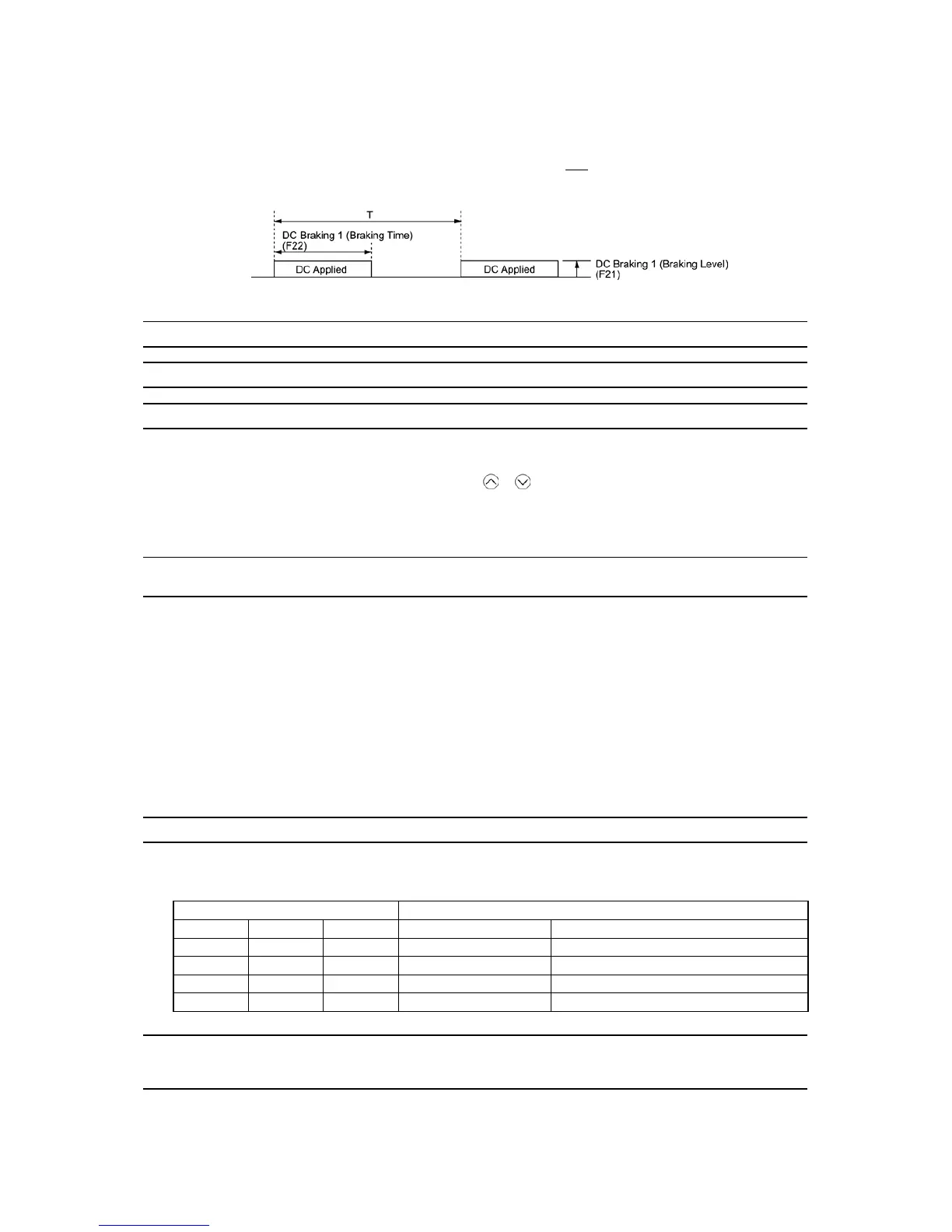
The magnitude of the DC power applied to the motor is the same as the setting of F21 (DC braking 1, Braking level)
and its duration of each interval is the same as the setting of F22 (DC braking 1, Braking time). Interval T is determined
so that the ratio of the duration of the DC power to T is the value (Duty) set for J21.
(%) 100×
T
F22
(J21) preventionon condensatifor Duty =
Condensation Prevention Cycle
J22 Commercial Power Switching Sequence (Refer to E01 through E07.)
J56 PID Control (Speed command filter)
J57 PID Control (Dancer reference position)
J57 specifies the dancer reference position in the range of -100% to +100% for dancer control.
If J02 = 0 (keypad), this function code is enabled as the dancer reference position.
It is also possible to modify the PID command with the
/ keys. If it is modified, the new command value is
saved as J57 data.
For the setting procedure of the PID command, refer to the FRENIC-MEGA User's Manual, Chapter 7, Section 7.3.3
"Setting up frequency and PID commands."
J58
J59 to J61
PID Control (Detection width of dancer position deviation)
PID Control (P (Gain) 2, I (Integral time) 2 and D (Differential time) 2)
The moment the feedback value of dancer roll position comes into the range of "the dancer reference position ±
detection width of dancer position deviation (J58)," the inverter switches PID constants from the combination of J03,
J04 and J05 to that of J59, J60 and J61, respectively in its PID processor. Giving a boost to the system response by
raising the P gain may improve the system performance in the dancer roll positioning accuracy.
Detection width of dancer position deviation (J58)
J58 specifies the bandwidth in the range of 1 to 100%. Specifying "0" does not switch PID constants.
P (Gain) 2 (J59) Data setting range: 0.000 to 30.000 (times)
I (Integral time) 2 (J60) Data setting range: 0.0 to 3600.0 (s)
D (Differential time) 2 (J61) Data setting range: 0.00 to 600.00 (s)
Descriptions for J59, J60, and J61 are the same as those of PID control P (Gain) (J03), I (Integral time) (J04), and D
(Differential time) (J05), respectively.
J62 PID Control (PID control block selection)
J62 allows you to select either adding or subtracting the PID dancer processor output to or from the primary speed
command. Also, it allows you to select either controlling the PID dancer processor output by the ratio (%) against the
primary speed command or compensating the primary speed command by the absolute value (Hz).
Data for J62 Control function
Decimal Bit 1 Bit 0 Control value type Operation for the primary speed command
0 0 0 Absolute value (Hz) Addition
1 0 1 Absolute value (Hz) Subtraction
2 1 0 Ratio (%) Addition
3 1 1 Ratio (%) Subtraction
J68 to J70
J71, J72
J95, J96
Brake Signal (Brake-OFF current, Brake-OFF frequency/speed and Brake-OFF timer)
Brake Signal (Brake-ON frequency/speed and Brake-ON timer)
Brake Signal (Brake-OFF torque and Speed selection)
These function codes are for the brake releasing/turning-on signals of vertical carrier machines.
It is possible to set the conditions of the brake releasing/turning-on signals (current, frequency or torque) so that a
hoisted load does not fall down at the start or stop of the operation, or so that the load applied to the brake is reduced.

 Loading...


