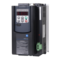
2-3
■
■■
■ Basic connection diagram
Basic connection diagram Basic connection diagram
Basic connection diagram
1) In case of using one DB unit and one braking resistor
Inverter DB unit
resistor
P(+)R
P(+)
N(-)
CHARGE
DB
G
G
1 2
i1 i2 o1 o2 1 2
Option
fan
P(+)
N(-)
alarm Input
(*1)
CM
Control circuit
Main circuit
P1
M
CN5,6
Wire length 5m or less
10m or less
SW1
1
2
3
P
DB
(*2)
++
(*4)
Fig. 2-3-2-1
2) In case of using two DB units and two braking resistors (
∗
3)
Inverter
P(+)
N(-)
(*1)
CM
Control circuit
Main circuit
P1
M
DB unit[Master]
resistor
P(+)R
P(+)
N(-)
CHARGE
DB
G
G
1
2
i1
i2
1
2
Option
fan
CN5,6
o1
o2
DB unit[Slave]
resistor
G
P(+)R
P(+)
N(-)
CHARGE
DB
G
1
2
i1
i2
1
2
Option
fan
CN5,6
o1
o2
1.5m or less
Wire length 5m or less
10m or less
SW1
1
2
3
SW1
1
2
3
P
DB
P
DB
(*2)
+
+
+
(*4)
Fig. 2-3-2-2
(∗1) Among the inverters. assignment to the digital input terminals can be arbitrarily changed
in some inverters. Select the external alarm input by function setting.
(∗2) Do not short-circuit the not using terminals of the control PCB in the DB unit.
(∗3) The parallel connection of the DB units is up to two units.
When necessary to connect 3 or more DB units, contact us separately.
(∗4) Connect a lump-sum alarm output of the DB unit and braking resistor to the external alarm
input, and construct a sequence to open the electromagnetic contactor by the lump-sum
alarm output of the inverter.
Applied inverter series
200V class
FRENIC5000 G5/P5,G7/P7,G9S/P9S
,G11S/P11S series
FRENIC-Eco
FRENIC5000 VG3,VG 5,VG7S
400V class
FRENIC5000 G9S/P9S
,G11S/P11S series
FRENIC-Eco
FRENIC5000 VG5,VG7S

 Loading...


