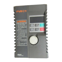
FVR-C11S-EN
2-2 2 Installation and Connection
2
2-2 Installation Method
1. Ti
htl
fasten the product in the upri
ht posi-
tion on a stron
structure usin
four bolts
(M4) with the characters FVR-C11 facin
the
front. Be sure not to turn the product upside
down, and install it on a horizontal surface.
2. Heat is
enerated while the inverter is operat-
in
, so the
aps shown in Fi
ure 2-2-1 are
necessar
for the passa
e of coolin
air. The
enerated heat is radiated upward b
the
built-in coolin
fan, so do not install this prod-
uct below a device that is sensitive to heat.
Fi
ure 2-2-1 Installation direction and surroundin
space
3. The temperature of the heat sink increases to
about 90 °C while the inverter is operatin
.
Therefore, the surface behind where the
product is located must be able to withstand
this temperature increase.
4. When installin
this product in a control pan-
el, carefull
consider the ventilation to pre-
vent the ambient temperature of the inverter
from exceedin
the specified value. Do not
install it in a hermeticall
sealed box from
which heat is not radiated full
.
5. If two or more inverters need to be installed in
the same device or control panel, the
should
be arran
ed horizontall
to minimize the influ-
ence of heat between them. If two or more in-
verters must be installed verticall
, place a
plate between them to prevent the upper in-
verter from bein
affected b
heat from the
lower inverter.
a) Horizontal arran
ement
b) Vertical arran
ement
Fi
ure 2-2-2 How to install two or more inverters
10cm
1cm FVR-C11 1cm
10cm
WARNING
Install this product on a nonflammable
material such as metal.
Otherwise fire could occur.
Inverter
Inverter
Air suppl
Air suppl
Air
suppl
Inverter
Plate
Inverter

 Loading...


