2-4 2 Installation and Connection
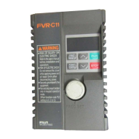
FVR-C11S-EN
2
2-3-2 Connectin
the main circuit and
round terminals
Table 2-3-1 Functions of main circuit and
round terminals
S
mbol Name Explanation
L1/L,L2/N Main power suppl
input Connects sin
le-phase power
(Sin
le-phase 200V input).
U, V, W Inverter output Connects 3-phase motor.
P1, P(+) For connection of DC
reactor
Connects input power- factor correctin
DC reactor
(optional).
P(+), N(-) For DC intermediate
circuit
Connected to DC link circuit terminal
(for DC bus connection).
G For inverter
roundin
Ground terminal for inverter chassis (case).
1) Main power suppl
input terminal
Sin
le-phase 200V [L1/L,L2/N]
Fi
ure 2-3-1 Arran
ement of main circuit and
round
terminals
1. Connect the main power suppl
input ter-
minals to the power suppl
via a molded
case circuit breaker for circuit protection or
earth leaka
e circuit breaker. An earth-
leaka
e circuit breaker which can also de-
tect DC current is recommended. Phase-
sequence matchin
is unnecessar
.
2. It is recommended that a ma
netic contac-
tor is connected to prevent an
failure or
accident from becomin
serious b
discon-
nectin
the inverter from the power suppl
when the inverter protective function oper-
ates.
3. Do not turn on or off the main power suppl
to start or stop the inverter; instead, use the
control circuit terminal FWD/REV or the
RUN/STOP ke
on the ke
pad panel. If it
is unavoidable to turn the main power sup-
pl
on or off to start or stop the inverter, it
must not exceed once per hour.
2) Inverter output terminal [U, V, W]
1. Connect these terminals to the 3-phase
motor with the correct phase-sequence. If
a motor rotation direction does not corre-
spond to the correct rotation direction, ex-
chan
e an
two of the U, V, and W phases.
2. Do not connect a phase-advance capaci-
tor or sur
e absorber to the inverter output.
3. A ver
lon
wirin
len
th between the in-
verter and the motor causes a hi
h fre-
quenc
current to flow due to floatin
capacit
between cables, makin
the in-
verter trip, increasin
the leaka
e current
and deterioratin
the accurac
in the cur-
rent displa
. To prevent such trouble, the
wirin
len
th to the motor should not ex-
ceed 50 meters.
When the inverter is operated in the low
noise mode (carrier frequenc
: 8 to 15
kHz) and the wirin
len
th is lon
, add an
optional output circuit filter (OFL filter).
GWVUN(-)P(+)
FVR-C11S-7EN
P(+)P1L2/NG L1/L
For sin
le-phase 200V input

 Loading...


