9 Specifications 9-11
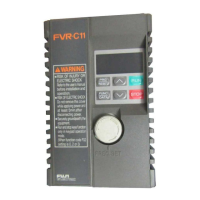
FVR-C11S-EN
9
Table 9-4-1 Peripheral device selection
9-4 Selection of
Peripheral
Device
It is recommended to use a prescribed wire accordin
to the EN60204
Appendix C.
Power supply voltage
Nominal applied motor (kW)
Inverter t
pe
Molded case cir-
cuit breaker
1
(MCCB)
Earth-leaka
e
circuit breaker
(ELCB or RCD)
rated current (A)
Ma
netic
contactor (MC)
Recommended wire size (mm
2
)
Input circuit
Sin
le-phase
200V
[L1/L, L2/N]
Output
circuit
[U,V,W]
Input circuit
Sin
le-phase
200V
[L1/L, L2/N]
Output circuit
2)
[U,V,W]
DCR circuit
2)
[P1][P(+)]
Control wiring
Usin
with
DCR.
Not
usin
with
reactor.
3
Usin
with
DCR.
Not
usin
with
reactor.
3
Usin
with
DCR.
Not
usin
with
reactor.
3
Single-phase 200V
0.1 FVR0.1C11S-7EN
6
6
SC-05
4
2.5
4
2.5
4
2.5
4
2.5
0.5
0.2 FVR0.2C11S-7EN
0.4 FVR0.4C11S-7EN 10
0.75 FVR0.75C11S-7EN 10 16
1.5 FVR1.5C11S-7EN 16 20
4
4.0
2.2 FVR2.2C11S-7EN 20 32 SC-5-1
5
4.0
5
6.0
5
2.5
5
4.0
1) The frame size and the series for the applicable molded-case circuit breaker
(MCCB) and earth-leaka
e circuit breaker (ELCB or RCD) differ accordin
to the
capacit
of transformer in the facilit
. Refer to each technical document for details.
2) The recommended wire size in the main circuit is for when the ambient
temperature is 40°C and conformin
to LVD requirements. The wire size in ( ) is
minimum size for IV wire when no necessar
of conformin
to LVD.
3) Power suppl
impedance without a reactor must be 0.1% or equivalent b
convertin
to the inverter capacit
. Based on the volta
e imbalance, a current
imbalance of 10% is expected.
4) Crimp terminals up to 7.4mm in width (includin
tolerance) can be used.
5) Crimp terminals up to 9.5mm in width (includin
tolerance) can be used.

 Loading...


