2 - 2
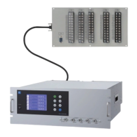
2.2 Input/Output terminal module
This analyzer provides input/output of various signals from the supplied input/outpt terminal
module by connecting the analyzer main unit to this module.
Fig. 2-2
Name 'HVFULSWLRQ Name 'HVFULSWLRQ
0RXQWLQJKROH 8VHGIRUPRXQWLQJLQSXWRXWSXW
terminal module.
ø 4.5, 6 places
&RQQHFWLRQFDEOH
between analyzer
main unit and
input/output
terminal module
8VHGIRUFRQQHFWLQJWKHDQDO\]HU
main unit to the input/output
terminal module.
(2) Input/output
terminal block
(TN 1 to TN 5)
Input/output terminal for
signals of analog output, range
LGHQWL¿FDWLRQFRQWDFWDODUP
contact output, etc.
&RQQHFWRUWR
relay board
&1!
&DEOHFRQQHFWRUIRUFRQQHFWLQJ
the analyzer to the relay board
for automatic calibration.
&RQQHFWRUWR
analyzer main
XQLW&1!
8VHGIRUFRQQHFWLQJWKHDQDO\]HU
main unit and the input/output
terminal module (4).
&RPPXQLFDWLRQ
connector
&1!
&RQQHFWFRPPXQLFDWLRQFDEOH
*Please refer to another manual
,1=71$(DERXW
communication function.
(5) Connector to relay board <CN3>
(3) Connector to analyzer main unit <CN1>
<Input/Output terminal module>
TN1 TN2 TN3 TN4 TN5
(1) Mounting hole (ø4.5, 6 places)
(2) Input/Output terminal block (TN1 to TN5)
(6) Communication connector (CN2)
(4) Connection cable between analyzer main unit and input/output terminal module (1m)
0
0 0 0
 Loading...