EasyManua.ls Logo

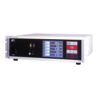
Fuji Electric ZRE-2 - Outline Diagram; Analyzer Main Unit Dimensions

Fuji Electric ZRE-2
85 pages
To Next Page IconTo Next Page
To Previous Page IconTo Previous Page
Loading...
77
INZ-TN2ZRE-E



INLET2 OUTLET2
OUTLET1INLET1PURGE
POWER INLET
100-240V AC
I
O
E
U
F
S
250VT2AL
FUSE
ESC
SPANMODE
ENTER
ZERO
POWER
GAS
ZRE
ANALYZERGAS
ZRE
ANALYZER
INLET2 OUTLET2
OUTLET1INLET1
A/O
PURGE
DIO3
DIO2
DIO1
RS485
A/I
MadeinJapan
INFRARED GAS ANALYZER
E
U
F
S
250VT2AL
FUSE
PE N L
AC
POWER
V
SOURCE
SER.NO.
POWER
OUTPUT
MFD
TYPE
100VA
50/60Hz
0-10/25%
AC100V-240V
DC4-20mA
0-200/2000ppm
0-1/10%
0-200/2000ppm
ZREABV41-CGCGJ-MCGC1DE-CFYAA
NO
SO2
CO2
CO
O2
0-200/2000ppm
A9P6146T
2009-12
<In case of UL model>
<Standard model>
<Standard model>
<In case of UL model>
384
132.5
149
Power Switch
124.5
A
Purge gas inlet Rc
1
/4 or NPT
1
/4
Sample gas inlet Rc
1
/4 or NPT
1
/4
Sample gas outlet Rc
1
/4 or NPT
1
/4
Sample gas inlet Rc
1
/4 or NPT
1
/4
Sample gas outlet Rc
1
/4 or NPT
1
/4
7
<Rear view>
Dimension A
JIS 50mm
EIA 57.2mm
435
Rubber boss for installing on a
table or the like
Communication
connector (RS485)
Analog external input
connector (A/I)
<Front view>
<Top view>
483
443
Power terminal (M4)
Analog output connector (A/O)
Digital input/output connector (DIO 1 to 3)

Table of Contents

Related product manuals