6
45
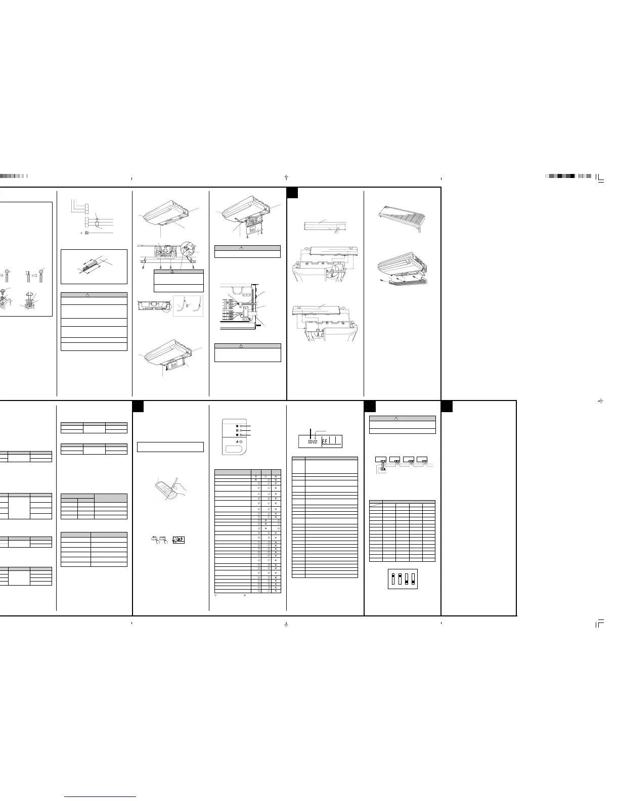
INDOOR UNIT SIDE
(1) Remove the electric component box.
Electric component box
Electric component box
Remove the four
tapping screws.
CAUTION
1 Do not remove the screws. If the stays
are removed, the electric component
box will fall.
2 If you use as “Floor console”, you must
remove screws and RFMs (2 positions).
(4) Wiring
1 Remove the cord clamp.
2 Process the end of the connection cords to the dimensions as shown
in the figure.
3 Connect the end of the connection cord fully into the terminal block.
Cord clamp
Cord clamp
(2) Pull out the electric component box.
Electric component box
(3) Remove the electric component box cover.
Electric component box cover
Remove the three tapping screws.
CAUTION
Be careful not to pinch the lead wires between the electric
component box and base.
Base
4 Fasten the connection cord with a cord clamp.
5 Fasten the end of the connection cord with the screw.
MOUNT THE COVER PLATE
AND THE INTAKE GRILLE
1. MOUNT THE COVER PLATE (RIGHT)
(1) Cut a pipe exit hole in the right plate. This is only when the pipe exits
from the right side. (This operation is not required when the protrusion
is on the top or rear.)
(2) Join the cover plates (right) and mount with the screw (ø4 × 10).
Cover plate (Right)
2. MOUNT THE COVER PLATE (LEFT)
Join the cover plates (left) and mount with the screw (ø4 × 10).
Cover plate (Left)
3. MOUNT THE INTAKE GRILLE
(1) Cut the r ight side of the intake grille. This is only when the pipe exits
from the right side.
(2) Inser t the hinges on the bottom of the intake grille into the holes in the
base assembly. Then mount the arms to the three areas on the top of
the intake grille.
A. Solid wire
Strip 25 mm (15/16")
Insulation
Loop
B. Strand wire
Strip 10 mm (3/8")
Round
terminal
Wire
Screw with
special washer
Round terminal
Terminal
board
Wire
Screw with
special washer
Round
terminal
HOW TO CONNECT WIRING TO THE TERMINALS
A. For solid core wiring
(1) Cut the wire end with a wire cutter or wire-cutting pliers, then strip
the insulation to about 25 mm (15/16") of expose the solid wire.
(2) Using a screwdriver, remove the terminal screw(s) on the terminal
board.
(3) Using pliers, bend the solid wire to form a loop suitable for the
terminal screw.
(4) Shape the loop wire proper ly, place it on the terminal board and
tighten securely with the terminal screw using a screwdriver.
B. For strand wiring
(1) Cut the wire end with a wire cutter or wire-cutting pliers, then strip
the insulation to about 10 mm (3/8") of expose the strand wiring.
(2) Using a screwdriver, remove the terminal screw(s) on the terminal
board.
(3) Using a round ter minal fastener or pliers, securely clamp a round
terminal to each stripped wire end.
(4) Position the round terminal wire, and replace and tighten the ter-
minal screw using a screwdriver.
ELECTRICAL WIRING
1. CONNECTION DIAGRAMS
Wired remote controller (option)
Control line
Indoor unit
side terminal
Power line
Red
White
Black
Power supply cord
or connection cord
30 mm
60 mm or more
Earth wire
WARNING
1 Before starting work, check that power is not being
supplied to the indoor unit and outdoor unit.
2 Match the terminal board numbers and connection
cord colors with those of the outdoor unit.
Erroneous wiring may cause burning of the electric
parts.
3 Connect the connection cords firmly to the terminal
board. Imperfect installation may cause a fire.
4 Always fasten the outside covering of the connection
cord with the cord clamp. (If the insulator is chafed,
electric leakage may occur.)
5 Always connect the ground wire.
6 Install the remote controller wires so as not to be di-
rect touched with your hand.
3. CONNECTION OF WIRING
• Use a 4-core wire cord.
Keep the earth wire longer than the other wires.
Connection cord
(to outdoor unit)
Wired remote
controller cord
(option)
CAUTION
Do not bundle the remote controller cord, or wire the re-
mote controller cord in parallel, with the indoor unit con-
nection wire (to the outdoor unit) and the power supply
cord. It may cause erroneous operation.
2. CONNECTION CORD PREPARATION
(5) Floor console / Under celing select switch
1 This unit was set for use as a ceiling type at the factor y.
2 When using the unit as a floor type, perfor m the following settings in
FUNCTION SETTING. (Refer to 7 FUNCTION SETTING.)
Setting the Cooler Room Temperature Correction
→Setting Value “01”
Setting the Heater Room Temperature Correction
→Setting Value “01”
87
FUNCTION SETTING
• Follow the instructions in the Local Setup Procedure, which is supplied
with the remote control, in accordance with the installed condition. After
the power is turned on, perform the Function Setting on the remote
control.
• The settings may be selected between the following two: Function
Number or Setting Value.
• Settings will not be changed if invalid numbers or setting values are
selected.
Setting the Ceiling Height
• Select the setting values in the table below according to the height of
the ceiling. (The unit is factory-set to “00”.)
Setting Value
00
01
Setting Description
Standard
High ceiling
Function Number
20
Jumper wire
JM2
Connect
Connect
Disconnect
Disconnect
Remote control unit
signal code
A (Primary setting)
b
c
d
JM1
Connect
Disconnect
Connect
Disconnect
When using floor console installation, don't need to change the setting value.
Setting the Filter Sign
• The indoor unit has a sign to inform the user that it is time to clean the
filter.
• Select the time setting for the filter sign display interval in the table
below according to the amount of dust or debris in the room. (The unit
is factory-set to “00”.)
• If you do not wish the filter sign to be displayed, select the setting value
for “No indication”.
Setting Value
00
01
02
03
Setting Description
Standard
(400 hours)
Long interval
(1,000 hours)
Short interval
(200 hours)
No indication
Function Number
11
Setting the Cooler Room Temperature Correction
• Depending on the installed environment, the room temperature sensor
may require a correction. The settings may be selected as shown in the
table below. (The unit is factory-set to “00”.)
Setting Value
00
01
Setting Description
Standard
Lower control
Function Number
30
Setting the Heater Room Temperature Correction
• Depending on the installed environment, the room temperature sensor
may require a correction. The settings may be changed as shown in the
table below. (The unit is factory-set to “00”.)
Setting Value
00
01
02
03
Setting Description
Standard
Lower control
Slightly warmer control
Warmer control
Function Number
31
Setting Other Functions
• The following settings are also possible, depending on the operating
conditions. (The unit is factory-set to “00”.)
Auto Restart
Setting Value
00
01
Setting Description
Ye s
No
Function Number
40
Indoor Room Temperature Sensor Switching Function (Wired remote con-
troller only)
Setting Value
00
01
Setting Description
No
Ye s
Function Number
42
• If setting value is “00”, room temperature is controlled by the indoor unit
temperature sensor.
• If setting value is “01”, room temperature is controlled by either indoor
unit temperature sensor or remote control unit sensor.
[When using the wireless remote controller]
SWITCHING REMOTE CONTROL UNIT SIGNAL
CODES
• Confirm the setting of the remote control unit signal code and the printed
circuit board setting.
If these are not confirmed, the remote control unit cannot be used to
operate for the air conditioner.
When using floor console installation, change the setting value to “01”.
When using floor console installation, change the setting value to “01”.
TEST RUN
CHECK ITEMS
(1) Is operation of each button on the remote control unit normal?
(2) Does each lamp light nor mally?
(3) Do not air flow direction louvers operate normally?
(4) Is the drain nor mal?
(5) Is there any abnor mal noise and vibration during operation?
• Do not operate the air conditioner in the running state for a long time.
• Test running
When the air conditioner is run by pressing the remote control unit test
run button, the OPERATION and TIMER lamps flash slowly at the same
time.
[Using the wireless remote control]
• For the operation method, refer to the operating manual.
• The outdoor unit may not operate depending on the room temperature.
In this case, press the test run button on the remote control unit while
the air conditioner is running. (Point the transmitter section of the re-
mote control unit toward the air conditioner and press the test run but-
ton with the tip of a ball-point pen, etc.)
Transmitter section
Test run button
•
To end test operation, press the remote control unit START/STOP button.
(When the air conditioner is run by pressing the test run button, the
OPERATION indicator lamp and TIMER indicator lamp will simultane-
ously flash slowly.)
[Using the wired remote control]
• For the operation method, refer to the operating manual.
(1) Stop the air conditioner operation.
(2) Press the master control button and the fan control button simultane-
ously for 2 seconds or more to start the test run.
(3) Press the star t/stop button to stop the test run.
Test run display
Setting
Ceiling height
Filter sign
Cooler room temperature
correction
Heater room temperature
correction
Auto restart
Indoor room temperature
sensor switching function
Setting Value
Setting record
• Record any changes to the settings in the following table.
[Troubleshooting at the remote control LCD]
This is possible only on the wired remote control.
[SELF-DIAGNOSIS]
If an error occurs, the following display will be shown.
(“EE” will appear in the set room temperature display.)
Unit number
Error code
Ex. Self-diagnosis
Error code Error contents
Indoor signal error
Wired remote controller abnormal
Indoor room temperature sensor error
Indoor heat exchanger temperature sensor (middle)
error
Indoor heat exchanger temperature sensor (inlet)
error
Float switch operated
Outdoor discharge pipe temperature sensor error
Outdoor heat exchanger temperature sensor (outlet)
error
Outdoor temperature sensor error
Compressor temperature sensor error
2-way valve temperature sensor error
3-way valve temperature sensor error
Outdoor heat exchanger temperature sensor (middle)
error
Indoor manual auto switch abnormal
Power supply frequency detection error
IPM protection
CT error
Compressor location error
Outdoor fan error
Connected indoor unit abnormal
Outdoor unit computer communication error
Indoor fan abnormal
Discharge temperature error
Exessive high pressure protection on cooling
4-way valve abnormal
Pressure switch abnormal
Compressor temperature error
Active filter abnormal
PFC circuit error
01
13
26
27
00
02
04
28
09
0C
06
0A
15
1d
1E
29
20
2A
17
18
1A
1b
1F
1c
12
0F
24
2c
16
2b
19
25
0
1
2
3
4
5
6
7
8
9
10
11
12
13
14
15
1
OFF
ON
OFF
ON
OFF
ON
OFF
ON
OFF
ON
OFF
ON
OFF
ON
OFF
ON
2
OFF
OFF
ON
ON
OFF
OFF
ON
ON
OFF
OFF
ON
ON
OFF
OFF
ON
ON
3
OFF
OFF
OFF
OFF
ON
ON
ON
ON
OFF
OFF
OFF
OFF
ON
ON
ON
ON
4
OFF
OFF
OFF
OFF
OFF
OFF
OFF
OFF
ON
ON
ON
ON
ON
ON
ON
ON
Unit number DIP SWITCH No.
9
SPECIAL INSTALLATION
METHODS
10
CUSTOMER GUIDANCE
Explain the following to the customer in accordance with the operating
manual:
(1) Star ting and stopping method, operation switching, temperature ad-
justment, timer, air flow switching, and other remote control unit op-
erations.
(2) Air filter removal and cleaning, and how to use the air louvers.
(3) Give the operating and installation manuals to the customer.
(4) If the signal code is changed, explain to the customer how it changed
(the system returns to signal code A when the batteries in the remote
control unit are replaced).
*(4) is applicable to using wireless remote control.
Indoor unit
Indoor signal error
Wired remote controller abnormal
Indoor room temperature sensor error
Indoor heat exchanger temperature
sensor (middle) error
Indoor heat exchanger temperature
sensor (inlet) error
Float switch operated
Outdoor discharge pipe temperature
sensor error
Outdoor heat exchanger temperature
sensor (outlet) error
Outdoor temperature sensor error
Compressor temperature sensor error
2-way valve temperature sensor error
3-way valve temperature sensor error
Outdoor heat exchanger temperature
sensor (middle) error
Indoor manual auto switch abnormal
Power supply frequency detection er-
ror
IPM protection
CT error
Compressor location error
Outdoor fan error
Connected indoor unit abnormal
Outdoor unit computer communication
error
Indoor fan abnormal
Discharge temperature error
Exessive high pressure protection on
cooling
4-way valve abnormal
Pressure switch abnormal
Compressor temperature error
Active filter abnormal
PFC circuit error
Error contents
OPERATION
lamp (Red)
(2 times)
(2 times)
(2 times)
(2 times)
(3 times)
(3 times)
(3 times)
(3 times)
(3 times)
(3 times)
(3 times)
(4 times)
(4 times)
(5 times)
(5 times)
(5 times)
(5 times)
(5 times)
(5 times)
(6 times)
(7 times)
(7 times)
(7 times)
(7 times)
(7 times)
(8 times)
(8 times)
TIMER lamp
(Green)
(8 times)
(2 times)
(3 times)
(4 times)
(6 times)
(2 times)
(3 times)
(4 times)
(8 times)
(2 times)
(4 times)
(2 times)
(3 times)
(5 times)
(6 times)
(7 times)
(8 times)
(2 or 3 times)
(2 times)
(3 times)
(4 times)
(5 times)
(6 times)
(2 or 3 times)
(4 times)
FILTER lamp
(Orange)
(2 times)
(3 times)
(4 times)
: 0.5s ON/0.5s OFF (Flash) : OFF
Troubleshooting
(Troubleshooting with the indoor display)
Troubleshooting at the display is possible either on the wired or wireless
remote control.
The OPERATION, TIMER and FILTER lamp operate as follows table ac-
cording to the error contents.
OPERATION lamp (Red)
TIMER lamp (Green)
FILTER lamp (Orange)
 Loading...