En-4
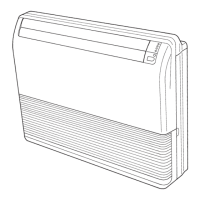
3.3.3. Barrier and RFM base removal and installation
(1) Remove the bar-
riers by removing
the 4 fixing screws
(2 screws each).
(2) Remove the RFM
base by removing
the 2 fixing screws
and unhooking the
1 hook.
(3) After completing
the work, install the
barriers and RFM
base as they were
originally. Install
the barriers in the
correct direction.
RFM base
Fixing screw
(2 positions)
Barriers
Fixing screw
(2 positions)
Hook
4. PIPE INSTALLATION
CAUTION
Be more careful that foreign matter (oil, water, etc.) does not enter the piping than with
refrigerant R410A models. Also, when storing the piping, securely seal the openings by
pinching, taping, etc.
While welding the pipes, be sure to blow dry nitrogen gas through them.
4.1. Selecting the pipe material
CAUTION
Do not use existing pipes from another refrigeration system or refrigerant.
Use pipes that have clean external and internal sides without any contamination which
may cause trouble during use, such as sulfur, oxide, dust, cutting waste, oil, or water.
It is necessary to use seamless copper pipes.
Material: Phosphor deoxidized seamless copper pipes It is desirable that the amount of
residual oil is less than 0.004 oz/100 ft (40 mg/10 m).
Do not use copper pipes that have a collapsed, deformed, or discolored portion (es-
pecially on the interior surface). Otherwise, the expansion valve or capillary tube may
become blocked with contaminants.
Improper pipe selection will degrade performance. As an air conditioner using R410A
incurs pressure higher than when using conventional (R22) refrigerant, it is necessary to
choose adequate materials.
• Thicknesses of copper pipes used with R410A are as shown in the table.
• Never use copper pipes thinner than those indicated in the table even if they are avail-
able on the market.
Thicknesses of
Annealed Copper
Pipes (R410A)
Pipe outside diameter [in (mm)] Thickness [in (mm)]
1/4 (6.35) 0.032 (0.80)
3/8 (9.52) 0.032 (0.80)
1/2 (12.70) 0.032 (0.80)
5/8 (15.88) 0.039 (1.00)
3/4 (19.05) 0.039 (1.20)
4.2. Pipe requirement
CAUTION
Refer to the Installation Manual of the outdoor unit for description of the length of con-
necting pipe or for difference of its elevation.
• Use pipe with water-resistant heat insulation.
CAUTION
Install heat insulation around both the gas and liquid pipes. Failure to do so may cause
water leaks.
Use heat insulation with heat resistance above 248°F (120°C). (Reverse cycle model
only)
In addition, if the humidity level at the installation location of the refrigerant piping is
expected to exceed 70 %, install heat insulation around the refrigerant piping.
If the expected humidity level is 70 to 80 %, use heat insulation that is 9/16 in (15 mm)
or thicker and if the expected humidity exceeds 80 %, use heat insulation that is 13/16
in (20 mm) or thicker. If heat insulation is used that is not as thick as specified, conden-
sation may form on the surface of the insulation.
In addition, use heat insulation with heat conductivity of 0.045 W/(m·K) or less (at 68°F
(20°C)).
B-1. Drilling for piping
Select piping and drain direc-
tions.
For direction
, bore the oval
hole shown in the following
figure.
CAUTION
Install the drain hose at the
rear; it should not be installed
on the top or right side.
Top
Rear (Install the drain
hose in this direction.)
Right
Hole
VIEW
When the directions are selected, drill 3-1/8 in
(80 mm) and 1-15/16 in (50 mm) or
5-7/8 in (150 mm) dia. hole on the wall so that
the hole is tilted downward toward the outdoor for
smooth water flow.
Unit: in (mm)
Wall
1/4 (6)
Indoor side Outdoor side
B-2. Drilling the holes and attaching the suspension bolts
Drill Φ1 in (25 mm) holes at the suspen-
sion bolt locations, then install the bolts.
Bolt Strength
220 to 330 lbf
(980 to 1470 N)
Φ 1 (25)
Unit: in (mm)
Ceiling panel
13/16 to 1-15/16
(20 to 50)
[If using anchor bolts]
Drill holes for anchor bolts at the loca-
tions at which you will set the suspen-
sion bolts. Note that anchor bolts are
M10 bolts (to be obtained locally).
Anchor-Bolt
Strength
220 to 330 lbf
(980 to 1470 N)
M10 Anchor bolt
(locally purchased)
Ceiling
13/16 to 1-15/16
(20 to 50)
Unit: in (mm)
B-3. Installing Brackets
Install the bracket with nuts, spring washers.
Bracket (right)
(accessories)
Bracket
Bracket (left)
(accessories)
Special nut A
(accessories)
Ceiling panel
Spring washer
(locally purchased)
M10 Nut (locally purchased)
M10 Nut (locally purchased)
B-4. Installing indoor unit
Reset the hex bolts as shown in the figure.
Unit: in (mm)
Indoor unit
Hex bolt
5/16 to 1/2
(8 to 13)
Apply the indoor unit to the
brackets.
Now, securely tighten the hex
bolts in both sides.
Indoor unit
Bolt
Bracket
9367701162-02_IM.indb Sec1:49367701162-02_IM.indb Sec1:4 27/09/2019 09:32:5727/09/2019 09:32:57
 Loading...


