En-4
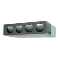
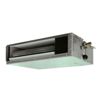
3.3.4. Outlet duct
Duct installation pattern ( CUT PART)
Round duct outlet u 4 (Factory setting.) Square duct
• When using the square duct, follow the procedure below to process outlet duct.
(1) Cut the slit seam
with a cutter.
(2) Turn up the insulation
around the points to be
cut according to the outlet
port shape working points
so that the insulation
does not stick out at the
part.
Cut
Cut
Cut
Cut
(3) Cut with nippers and remove the sheet metal.
• The screw holes to install the flange
are located behind the round cutouts
in the insulation.
CAUTION
To prevent people from touching the parts inside the unit, be sure to install grilles on
the inlet and outlet ports. The grilles must be designed in such a way that cannot be
removed without tools.
The static pressure outside the unit is as follows.
ARUM24/30/36 Model: 0.12 to 0.60 in WG (30 to 150 Pa)
If an intake duct is installed, take care not to damage the temperature sensor (the
temperature sensor is attached to the intake port flange).
Install the air inlet grille
for air circulation. The
correct temperature
cannot be detected.
Unit
Outlet Grille
(locally purchased)
Inlet Grille
(locally purchased)
(Room)
Duct
(locally purchased)
Be sure to install the air filter in the air inlet. If the air filter is not installed, the heat
exchanger may be clogged and its performance may decrease.
WARNING
When fastening the hangers, make the bolt positions uniform.
The distance of
is adjustable according to the place of the hanging bolts.
(MAX.: 21-5/8 in (550 mm), MIN.: 16-1/8 in (410 mm))
Slide the unit in the arrow direction and fasten it.
Hanging bolt M10
(locally purchased)
Special nut A (accessories)
Washer (locally purchased)
Special nut B (accessories)
Hanger (accessories)
Bolt Strength 86.8 to 130.2 lbf·in (9.81 to 14.71 N·m)
WARNING
Fasten the unit securely with special nuts A and B.
3.3.2. Leveling
Base vertical direction leveling on the
unit (right and left).
(Right side)
Level
AIR
AIR
Base horizontal direction
leveling on top of the unit.
Give a slight tilt to the side
to which the drain hose is
connected. The tilt should
be in the range of 0 to
0.19 in (0 to 5.0 mm).
Drain hose
0 to 0.19 in
(0 to 5.0 mm)
3.3.3. Intake duct
Follow the procedure in the follow-
ing figure to the ducts.
39-15/16 in (1015 mm)
9-7/16 in
(240 mm)
The air inlet duct can be changed by replacing the intake grille and flange. For the bottom
air intake, follow the procedure of ① → ② for installation. (The factory setting is back air
intake.)
①
②
CAUTION
When air is taken in from the bottom side, the operating sound of the product will easily
enter the room.
Install the product and intake grilles where the effect of the operating sound is small.
9373385264-02_IM_L3.indb Sec1:49373385264-02_IM_L3.indb Sec1:4 9/24/2019 11:06:29 AM9/24/2019 11:06:29 AM
 Loading...