¢
System diagram
• For connecting single split type system
Group of Single Split System*
1
Single Split
System
VRF system
To outdoor
units
Multi System*
2
(2 to 4 rooms multi )
(8 rooms multi)
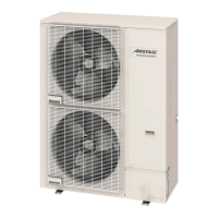
Outdoor unit for
single split / multi system
Indoor unit
Touch panel
controller
Wired remote
c
ontroller
Transmission line
(
non-polar 2-conductor)
Remote
c
ontroller line
Network
convertor
Multi System*
2
Branch
box
Outdoor unit for
Multi system
*1: All indoor units connected to a Network convertor are operated under same status.
*2: Network convertor
is necessary for each indoor unit to control indoor unit individually.
¢
E
lectrical wiring
L N
POWER
X1 X2
TRANSMISSION
Y1 Y2 Y3 J1
REMOTE INDOOR UNIT
REMOTE CONTROLLER LINE
J2 J3
1Ø 50/60 Hz
208-240 V
Switch
Fuse (3 A)
Transmission cable to VRF System Transmission cable to VRF System
Wired remote controller
Indoor unit
Power supply
Network convertor
RC cable to
indoor unit
RC cable
to RC
Transmission cable
Power
supply
3-2. Network convertor (UTY-VGGXZ1) - (05-116) - 3. Adaptor/Convertor units
CONTROL
SYSTEM
CONTROL
SYSTEM
 Loading...