WARNING
1 Before starting work, check that power is not being
supplied to the indoor unit and outdoor unit.
2 Match the terminal board numbers and connection
cord colors with those of the outdoor unit.
Erroneous wiring may cause burning of the electric
parts.
3 Connect the connection cords firmly to the terminal
board. Imperfect installation may cause a fire.
4 Always fasten the outside covering of the connection
cord with the cord clamp. (If the insulator is chafed,
electric leakage may occur.)
5 Always connect the ground wire.
PART NO. 9374872015
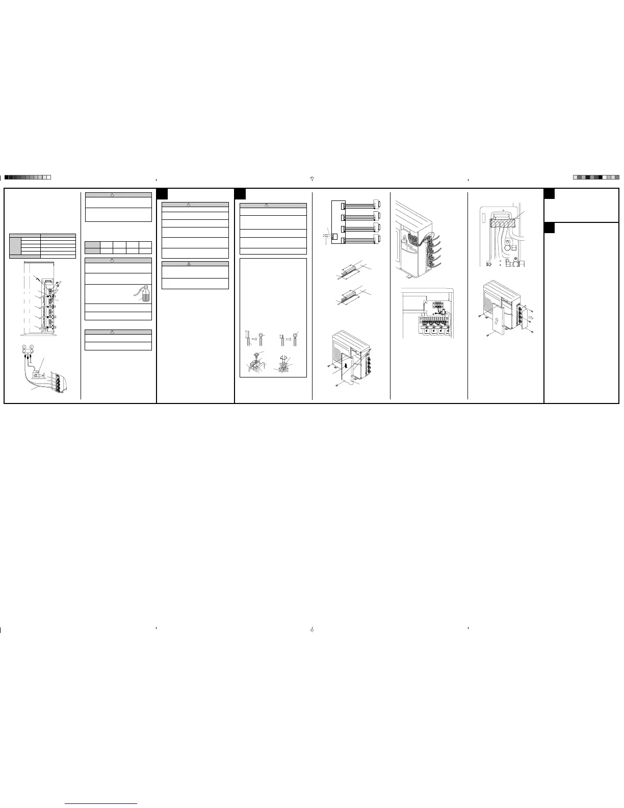
HOW TO CONNECT WIRING TO THE
TERMINALS
A. For solid core wiring (or F-cable)
(1) Cut the wire end with a wire cutter or wire-cutting pliers, then strip
the insulation to about 25 mm to expose the solid wire.
(2) Using a screwdriver, remove the terminal screw(s) on the terminal
board.
(3) Using pliers, bend the solid wire to form a loop suitable for the
terminal screw.
(4) Shape the loop wire properly, place it on the terminal board and
tighten securely with the terminal screw using a screwdriver.
B. For strand wiring
(1) Cut the wire end with a wire cutter or wire-cutting pliers, then strip
the insulation to about 10 mm to expose the strand wiring.
(2) Using a screwdriver, remove the terminal screw(s) on the terminal
board.
(3) Using a round terminal fastener or pliers, securely clamp a round
terminal to each stripped wire end.
(4) Position the round terminal wire, and replace and tighten the
terminal screw using a screwdriver.
A. Solid wire
Strip 25 mm
Insulation
Loop
B. Strand wire
Strip 10 mm
Round
terminal
Wire
Screw with
special washer
Round terminal
Terminal
board
Wire
Screw with
special washer
Round
terminal
Terminal block
4
ELECTRICAL WIRING
3
1. CONNECTION DIAGRAMS
3. OUTDOOR UNIT
(1) Service cover removal
• Remove the two mounting screws.
• Remove the service cover by pushing downwards.
Direction of the service
panel removal
Service cover
(2) Connect the power supply cord and the connection cord to terminal.
(3) Fasten the power supply cord and connection cord with cord clamp.
6
CUSTOMER GUIDANCE
Explain the following to the customer in accordance with the operating
manual:
(1) Starting and stopping method, operation switching, temperature
adjustment, timer, air flow adjustment, and other remote control unit
operations.
(2) Air filter removal and cleaning.
(3) Give the operating manual and installation instruction sheet to the
customer.
2. CORD PREPARATION
Keep the earth wire longer than the other wires.
Power supply cord
(5) Put the service cover and valve cover back after completion of the
work.
Hook
(3 places)
30 mm
100 mm or more
Earth wire
POWER
WARNING
1 The rated voltage of this product is 220-240 V A.C. 50 Hz.
2 Before turning on verify that the voltage is within the
198 V to 264 V range.
3 Always use a special branch circuit and install a spe-
cial receptacle to supply power to the air conditioner.
4 Use a special branch circuit breaker and receptacle
matched to the capacity of the air conditioner.
(Install in accordance with standard.)
5 Perform wiring work in accordance with standards so
that the air conditioner can be operated safely and posi-
tively.
6 Install a leakage special branch circuit breaker in ac-
cordance with the related laws and regulations and elec-
tric company standards.
CAUTION
1 The power source capacity must be the sum of the air
conditioner current and the current of other electrical
appliances. When the current contracted capacity is in-
sufficient, change the contracted capacity.
2 When the voltage is low and the air conditioner is diffi-
cult to start, contact the power company the voltage
raised.
(4) Be sure to seal the holes when applying the putty.
Place the cords side by side. (Do not overlap the cords.)
Putty
CAUTION
1 After connecting the piping, check the all joints for gas
leakage with gas leak detector.
2 When inspecting gas leakage, always use the vacuum
pump for pressure. Do not use nitrogen gas.
7. GAS LEAKAGE INSPECTION
6. ADDITIONAL CHARGE
Refrigerant suitable for a total piping length of 50 m is charged in the
outdoor unit at the factory.
When the piping is longer than 50 m, additional charging is necessary.
For the additional amount, see the table below.
50 m 60 m 70 m
(164 ft) (197 ft) (230 ft)
None
250 g 500 g 25 g/m
(8.8 oz) (17.6 oz) (0.9 oz/ft)
Total piping
length
Additional
refrigerant
Gas
Liquid
R410A
CAUTION
1 When moving and installing the air conditioner, do not
mix gas other than the specified refrigerant (R410A)
inside the refrigerant cycle.
2 When charging the refrigerant R410A, always use an
electronic balance for refrigerant charging (to meas-
ure the refrigerant by weight).
3 When charging the refrigerant, take
into account the slight change in the
composition of the gas and liquid
phases, and always charge from the
liquid phase side whose composi-
tion is stable.
4 Add refrigerant from the charging valve after the com-
pletion of the work.
5 If the units are further apart than the maximum pipe
length, correct operation can not be guaranteed.
5. VACUUM
(1) Remove the cap, and connect the gauge manifold and the vacuum
pump to the charging valve by the service hoses.
(2) Vacuum the indoor unit and the connecting pipes until the pressure
gauge indicates –0.1 MPa (–76 cmHg).
(3) When –0.1 MPa (–76 cmHg) is reached, operate the vacuum pump
for at least 30 minutes.
(4) Disconnect the service hoses and fit the cap to the charging valve to
the specified torque.
(5) Remove the blank caps, and fully open the spindles of the 2-way
and 3-way valves with a hexagon wrench [Torque: 6~7 N·m (60 to
70 kgf·cm)].
(6) Tighten the blank caps of the 2-way valve and 3-way valve to the
specified torque.
Tightening torque
20 to 25 N·m (200 to 250 kgf·cm)
20 to 25 N·m (200 to 250 kgf·cm)
25 to 30 N·m (250 to 300 kgf·cm)
30 to 35 N·m (300 to 350 kgf·cm)
35 to 40 N·m (350 to 400 kgf·cm)
10 to 12 N·m (100 to 120 kgf·cm)
Blank cap
6.35 mm (1/4 in.)
9.52 mm (3/8 in.)
12.70 mm (1/2 in.)
15.88 mm (5/8 in.)
19.05 mm (3/4 in.)
Charging port cap
Blank cap
Cap
Hexagon wrench
Charging port
Service hose
with valve core
Service hose
with valve core
Service hose
with valve core
Service hose
with valve core
Spindle
Gauge manifold
Service hose
Vacuum pump
 Loading...