ETERNUS DX80 S2/DX90 S2 Disk storage system User’s Guide -Installation-
Copyright 2013 FUJITSU LIMITED P3AM-4832-07ENZ0
14
List of Figures
Figure 1.1 LAN control (switching of the Master CM) ................................................................................................... 17
Figure 1.2 LAN control (when the IP address of the Slave CM is set) ............................................................................ 18
Figure 1.3 Connection example without a dedicated remote support port................................................................... 19
Figure 1.4 Connection example with a dedicated remote support port ........................................................................ 20
Figure 1.5 Connection example when the IP address of the Slave CM is set
(and a dedicated remote support port is not used) ..................................................................................... 21
Figure 1.6 Connection example when the IP address of the Slave CM is set
(and a dedicated remote support port is used) ........................................................................................... 22
Figure 1.7 Attaching Network Settings label ................................................................................................................ 25
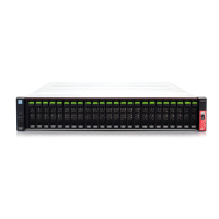
Figure 2.1 Front view of a 2.5" type controller enclosure.............................................................................................. 27
Figure 2.2 Front view of a 3.5" type controller enclosure.............................................................................................. 27
Figure 2.3 Rear view of a controller enclosure (single-controller type) ........................................................................ 28
Figure 2.4 Rear view of a controller enclosure (dual-controller type) ........................................................................... 28
Figure 2.5 Operation panel (2.5" type controller enclosure)......................................................................................... 29
Figure 2.6 Operation panel (3.5" type controller enclosure)......................................................................................... 29
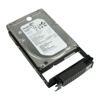
Figure 2.7 2.5" drive..................................................................................................................................................... 31
Figure 2.8 Drive slot numbers (2.5" type controller enclosure)..................................................................................... 31
Figure 2.9 3.5" drive..................................................................................................................................................... 31
Figure 2.10 Drive slot numbers (3.5" type controller enclosure)..................................................................................... 31
Figure 2.11 Controller .................................................................................................................................................... 32
Figure 2.12 Host interface (FC, iSCSI 10Gbit/s, FCoE (for FC cable connection)).............................................................. 34
Figure 2.13 Host interface (iSCSI 10Gbit/s, FCoE (for Copper Twinax cable connection)) ................................................ 35
Figure 2.14 Host interface (iSCSI 1Gbit/s)....................................................................................................................... 35
Figure 2.15 Host interface (SAS) .................................................................................................................................... 36
Figure 2.16 Power supply unit........................................................................................................................................ 37
Figure 2.17 Front view of a 2.5" type drive enclosure ..................................................................................................... 38
Figure 2.18 Front view of a 3.5" type drive enclosure ..................................................................................................... 38
Figure 2.19 Rear view of a drive enclosure (single-IOM type) ........................................................................................ 39
Figure 2.20 Rear view of a drive enclosure (dual-IOM type)........................................................................................... 39
Figure 2.21 LEDs on the front side of the drive enclosure .............................................................................................. 40
Figure 2.22 2.5" drive..................................................................................................................................................... 40
Figure 2.23 Drive slot numbers (2.5" type drive enclosure)............................................................................................ 41
Figure 2.24 3.5" drive..................................................................................................................................................... 41
Figure 2.25 Drive slot numbers (3.5" type drive enclosure)............................................................................................ 41
Figure 2.26 I/O module .................................................................................................................................................. 42
Figure 2.27 Power supply unit........................................................................................................................................ 43
Figure 2.28 Power distribution unit for DX80 S2/DX90 S2 (AC200-240V, 1U Max 2 enclosures connection)................... 44
Figure 2.29 Power distribution unit for DX80 S2/DX90 S2 (AC200-240V, 2U, Max 6 enclosures connection).................. 45
Figure 2.30 Power distribution unit for DX80 S2/DX90 S2 (AC200-240V, 2U, Max 8 enclosures connection).................. 46
Figure 5.1 PC terminal connection for initial setup....................................................................................................... 89
Figure 5.2 Overview of the AIS Connect function ........................................................................................................ 133
Figure 5.3 Security features........................................................................................................................................ 134

 Loading...