Ver.01
ICEMATIC
CYCLIC TIMER
6. WIRING DIAGRAM
1. DESCRIPTION
2. APPLICATION
3. SPECIFICATIONS
Icematic is a cyclic timer configurable through its setting keys which allow you to set up to 12 hours
output ON and 60 minutes output OFF. Its user-friendly interface accurately displays the configuration
through a set of LEDs. The panel also includes a key for manual inversion of output relay state. Its new
design allows DIN rail mounting or screw fixing.
It has protection when powered by connecting the output only after 2 minutes, during which time the LED
status indicator NO (normally open) will flash.
ICEMATIC can be used to time any kind of cyclic event, such as controlling defrosting and refrigeration
cycles in frigorific chambers/counters, or activating lamps, air conditioners and other appliances. When
used for irrigating it controls the activation of water circulation pumps or a hydraulic solenoid valve.
115or230Vac ± 15% (50/60Hz)
±2%
1 to 12 hours in 1-hour increment
5 to 60 minutes in 5-minute increments
16(8)A/ 250Vac1HP
77 x 39 x 97mm (approx. 3 03 x 1 53 x 3 82 inches)
-Power Supply:
-Accuracy:
-Output ON time:
-Output OFF time:
-Max. Current:
-Dimensions (WxDxH): . . .
Product complies with ULInc. (United States and Canada).
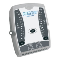
Output ON time
indicator LEDs
Output OFF time
indicator LEDs
Output ON time
selection key
Output OFF time
selection key
Output NO state
indicator LED
Output NC state
indicator LED
5. DISPLAY IDENTIFICATION AND CONTROL BUTTONS
4. SETTINGS
4.1 Output ON time setting
4.2 Output OFF time setting
4.3 Output ON/OFF reversion
Press the key for 3 seconds. The Output ON Time indicator LED starts blinking. Set the desired
time through the same key.The new setting is configured when the LED stops blinking.
Press the key for 3 seconds. The Output OFF Time indicator LED starts blinking. Set the desired
time through the same key.The new setting is configured when the LED stops blinking.
Use the key to manually select the output mode.After starting the Output OFF mode, if the
key is pressed inside 2 minutes the NO (Normally Open) state indicator LED starts blinking and the
output is turned ON only after this time is elapsed.
/
State reversion key
Power
supply
0
5-6 115V
5 - 7 230V
115V
230V
WALL
8.2
Screw fixation (wall-mounted)
HOLES
FOR
SCREW
FIXING
Screws for fixation
(not included)
7.1 For controlling refrigeration and
defrosting times.
Load
Defrosting
resistance
Compressor
Contactor switch
Solenoid bobbin
7.2 For controlling swimming pools,
exhaust, tunnels or irrigation
Load-1
Loads
supply
Load-1
Load-2
Load-
2
7. LOAD CONNECTION
Compressor
Contactor switch
Solenoid bobbin
Load
supply
DIN RAIL
WALL
8. INSTRUMENT FIXATION MODE
Wall
DIN rail
Instrument
Spare reinforce screws
(not included)
8.1
DIN mount fixation
1
2
NEWICEMATIC01-02T-11858
E251415