REPLACEMENT INSTRUCTIONS
CAPACITOR INSTALLATION KIT OP05-143
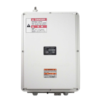
AT-1575 ANTENNA COUPLER PCB
These instructions cover how to replace the PCB of AT-1575 antenna coupler for the SSB Radio
Telephone FS-1575.
Note: Check the PCB version before replacement. The replacement board should be ordered
before proceeding with these instructions.
The new board 05P0883-22 (Code: 000-176-005-12) is not included with this kit.
Where the new board is already installed in the AT-1575, board replacement is not required.
Replacement kit
The contents of the kit are listed in the following table.
Capacitor Installation Kit OP05-143 (Code: 001-476-140)
How to remove the old PCB
1. Unfasten the pan head screws (M4x14, 8 pcs.), then remove the cover.
Fig.1: Antenna Coupler AT-1575
Name Type Code Qty.
Fixing Plate 05-062-0253 100-199-261-10 1
Clamp CKN-05 000-193-375-10 1
Washer Head Screw M4x6 000-163-176-10 2
Wire Assembly (Type AF) AF1160GG-L100 001-482-240 1