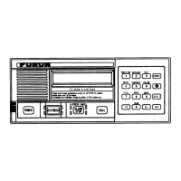
5-12
MODEM
The loopback test with DSC signal is executed. Connect LINE IN to LINE OUT at RT port connector.
If the test result is good, “OK” is displayed. If not, “NG” is displayed.
RX-1RX-1
RX-1RX-1
RX-1
DSC watch keeping receiver baord is tested. If the test result is good, “OK” is displayed. If not, “NG” is
displayed. The 18 MHz carrier signal inputs to the antenna circuit through the capacitive coupling of the
printed circuit pattern. For the test, 3rd local oscillator frequency is shifted by +85 Hz to generate the
mark signal of “1700Hz-85 Hz” and the space signal of “1700Hz+85 Hz”. If the MODEM can
recognize these signals, OK is displayed.
RX-2RX-2
RX-2RX-2
RX-2
Daily test of DSC general watch keeping receiver board is executed. The test method is the same as that
of above RCV1.
PRINTERPRINTER
PRINTERPRINTER
PRINTER
Printing of all the alphanumeric characters is tested to check the printing condition. The “NG” display
means that the data communication with the printer has not made normally.
Printer testPrinter test
Printer testPrinter test
Printer test
0123456789
ABCDEFGHIJKLMNOPQRSTUVWXYZ
abcdefghijklmnopqrstuvwxyz
3. Test through the Setup Menu
MAIN CPU DSP CODEC
LINE IN
LINE OUT
RT PORT
MODEM
#10-12
#11-13
J2
SYN
18MHz
ANT
Co
RF
(1700Hz + 85Hz)
RX(05P0703)
CONTROL/MODEM
(05P0702)
MODEM
MAIN CPU
DATA
LINE OUT
(SNY-DATA,TEST,FIL-SEL)
456.7kHz + 85Hz
3Lo
 Loading...