7.4 Control Unit
7-71
7.4 Control Unit
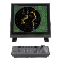
Models RCU-014, RCU-015 and RCU-016 are available for the control units RCU-014
and RCU-015 have a power switch. RCU-016 does not have a power switch and is used
for a remote control unit for RCU-014 or RCU-015. They are connected in series. When
two control units are used, operation from each control unit is at the same level.
Table 7.4.1 Overview of control unit
Component
RCU-014
(STD CONTROL)
RCU-015
(TRACKBALL)
RCU-016
(REMOTE)
Power supply With With Without
Control key switch
With
all key switches
F1 to F4 only
CONTROL board 03P9343 03P9344
BUZZER board 03P9362
TRACK BALL
model
TA4726N
Program Common
For connection between units, connect the [PROCESSOR] side with a higher-level unit.
The interface is RS-422 based on asynchronous communication method (19,200 bps).
Alarm sounds and panel brilliance data are outputted from RPU-013 to the control unit,
and key and control knob information and track ball data re outputted from the control
unit to RPU-013. The cable length from RPU-013 to the last control unit is 31 m at
longest taking supply voltage drop into consideration.
Fig. 7.4.1 Overview of connection
RPU-013
(RADAR PROCESSOR UNIT)
RCU-014 (STD CONTROL UNIT)
J602
J501
J502
KEY
TB p.c.b
PROCESSOR
REMOTE
RCU-015 (TRACKBALL UNIT)
J521
J522
PROCESSOR
REMOTE
RCU-015 (REMOTE UNIT)
J521
J522
PROCESSOR
REMOTE
TX/RX dat
SYS FAIL
PWR SW
+12V
TX/RX dat
+12V
 Loading...