2. WIRING
RG-10/U-Y
PREAMP
FAX-5
TX/RX ANTENNA
or TX ANTENNA
AUTOMATIC ANTENNA
SWITCH AS-102
RX ANTENNA
3D-2V
RG-10/U-Y
ANTENNA COUPLER
AT-5075
05S0952 or 05S0793
DPYC-1.5*
1
(or DPYCY-1.5*
1
)
TTYCS-4*
1
/
TTYCSLA-4*
1
ALARM UNIT
IC-350
TTYCS-1*
1
/
TTYCSLA-1*
1
100/110/120/200/
220/240 VAC
DPYC-6*
1
24 VDC
DPYC-16*
1
AC-DC POWER
SUPPLY UNIT
PR-850A
DPYC-16*
1
24 VDC
Ground
Wire
GPS NAVIGATOR*
2
(Ex. GP-150)
MATCHING BOX ARD-1 or
ANT. JUNC. BOX AJB1-1A
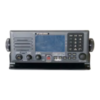
CONTROL UNIT
FS-2575C
PRINTER
I/F KIT IF-8500
or PRINTER
HANDSET
HS-2003
Ground
Wire
LOUDSPEAKER
DSUB15-5P-LxxM
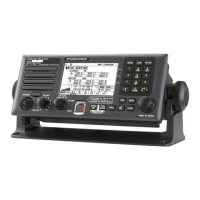
TRANSCEIVER UNIT
FS-5075T
NBDP TERMINAL IB-585
05S9351
Ground
Wire
External Switch
䠄
user supply
䠅
㻹㻼㼅㻯㻙㻞
Copper strap
(Connect
to ground.)
Supplement
ground wire
*3
Supplement
ground wire
*3
*
1
:
JIS cable. See Appendix for equivalent cable.
*
2
:
Connect the GPS navigator to the GNSS port of the transceiver unit.
When you set the AMS mode to [AlertIF1] or [AlertIF2], connect an AMS or sensor adaptor
that can output GPS information to the GNSS port.
*
3
:
It is recommended to add a supplement ground wire (local supply, more than 14 sq.) and
fasten it to the ground terminal of the antenna coupler.
Keyboard (IB-585)
5139U or 5139U BLACK
 Loading...