2. WIRING
2-13
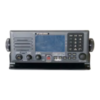
2.3 Control Unit
Connect the Transceiver Unit to the Control Unit with the cable with the D-sub 15-pin
connector on one end. Connect a single Control Unit to the CONTROLLER 1 port.
(This port has priority when two Control Units are connected.) Connect a No.2 Control
Unit to the CONTROLLER 2 port.
Connect the handset HS-2003 to the HANDSET port at the front of the Control Unit.
For other handset, connect to the HANDSET REAR port.
2.4 External Equipment
Connect cables for external equipment to the T-IF Board in the Transceiver Unit.
GNSS
This radiotelephone can receive the following sentences in IEC 61162-1 (ed.2nd) for-
mat. Use the cable TTYCS-1/TTYCSLA-1 (or the equivalent) to connect the equip-
ment to IEC 61162-1 of TB6 in the Transceiver Unit.
Alarm Unit IC-350
Connect the Alarm Unit IC-350 to TB7 in the Transceiver Unit with the cable TTYCS-
4/TTYCSLA-4 (or the equivalent).
Data Sentence, priority order
Position info, Position fix GNS>GGA>RMC>GLL
Time info ZDA>RMC
Braided shield
Sheath
Armor
Make hole here, pull out core and
cut off inclusion.
8 - 10
40 20
60
20 30 20
Set this part in cable clamp.
Crimp-on
lug
Vinyl tape
L
Tape entire
shield
Fabrication of TTYCS series
Length of “L”
FS-1575T
FS-2575T/FS-5075T
190
120
 Loading...