8. INSTALLATION
8-25
8.5 Installation, Adjustment of Optional Display Unit
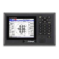
DS-600
The Display Unit GS-1002 can be connected with the optional DS-600.
8.5.1 Installation of the display unit DS-600
Mounting considerations
The display unit DS-600 can be installed on a desktop, on the underside of a table, or
flush mounted in a panel. When you select a mounting location, keep in mind the fol-
lowing points:
• Locate the display unit away from exhaust pipes and vents.
• Select an installation location that is well ventilated.
• Locate the display unit where shock and vibration are minimal.
• Allow enough maintenance space at the sides and rear of the display unit and leave
enough slack in cables to facilitate maintenance and servicing.
• Observe the compass safe distances (see page i) to prevent the interference to a
magnetic compass.
• The nominal viewing distance for the display unit is 1 m. Select a suitable mounting
location considering that distance.
Flush mount
See the outline drawing in the back of this manual. Before you fasten the display unit
to the cutout, first connect the cable to the DATA1/DATA2 port of the display unit GS-
1002. (See paragraph 8.2.2.)
1. Make a cutout in the mounting location as shown in the illustration below.
Note: Dimensions for the cutout are different depending on the mounting location,
indoor or outdoor. For the outdoor mounting, ask dockyard to construct a water-
proof case for the display unit.
2. Make four pilot holes for tapping screws (diameter: 5 mm) in the location indicated
in the illustration at step 1.
3. Insert the sponge to the display unit from the rear side.
4. Set the display unit to the cutout and fasten the display unit with four tapping
screws (5×20).
223±0.5 (8.78”)
228±1 (8.98”)
(for outdoor)
232±1 (9.13”)
(for indoor)
18 (0.71”)
228±1 (8.98”)
(for outdoor)
232±1 (9.13”)
(for indoor)
223±0.5 (8.78”)
Pilot hole
(four places)
18 (0.71”)
(for outdoor)
22 (0.87”)
(for indoor)
or
240 (9.45”)
Fixing hole (4-ø6)
240 (9.45”)
12 (0.47”)
78 (3.07”)
 Loading...