1
1. MOUNTING
NOTICE
Do not apply paint, anti-corrosive sealant
or contact spray to coating or plastic
parts of the equipment.
Those items contain organic solvents that
can damage coating and plastic parts,
especially plastic connectors.
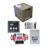
1.1 System Overview
The basic VDR consists of
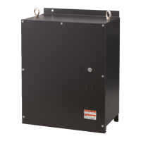
• Data Collecting Unit (DCU)
• Data Recording Unit (DRU) in the protective capsule
• Remote Alarm Panel (RAP) which indicates the status of the system remotely.
• Junction Box (JB) which can minimize the cable run and increase the number of the input
ports. (Optional supply with VR-3000S.)
• Bridge microphone (one supplied, max. 6)
• Optional VHF Interface Unit IF-5200 which combines VHF microphone and loudspeaker
lines.
The VDR system continuously stores data over past 12 hours in the DRU and removable hard
disk. Oldest data is erased as new data is entered.
The VDR operates on 100-230 VAC mains and 24 VDC power supply. In case of ship’s mains
failure, backup batteries are used for recording bridge audio for 2 hours.
A lot of sensors are connected to the VDR, in different signal types in some cases. Determine
all sensors to be connected before installation.
Note: The Data Collecting Unit, Data Recording Unit, Remote Alarm Panel and Junction Box
are sometimes referred to by their acronyms.
Data Collecting Unit: DCU
Data Recording Unit: DRU
Remote Alarm Panel: RAP
Junction Box: JB

 Loading...