2. WIRING
2-15
6. Reattach the cover to the junction box.
7. To prevent water from entering into the unit, apply the supplied silicone sealant
(KE-347-W-100) to cable entrances (three locations).
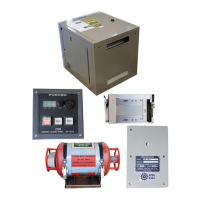
2.4 Remote Alarm Panel VR-7017
Connect wiring to the terminal board of the unit, referring to the interconnection dia-
gram at the back of this manual. See appendix 2 for how to fabricate the cable. After
wiring the cable, fix the cable with the cable clamp.
Note: When you connect between the DCU and remote alarm panel, see "Notice for
the connection with the remote alarm panel" on page 2-4.
Secure the shield (armor) of the FR-FTPC-CY cable to the junction
box chassis.
Secure the shield (drain wire) of the float-free DRU and the shield
(armor) of the DPYCY-1.5 cable to the junction box chassis.
Secure the shield (drain wire) of the float-free DRU and the shield
(armor) of the DPYCY-1.5 cable to the junction box chassis.
10
10
10
Remote alarm panel (back cover removed)
Pin No. Signal In/Out
1
2
3
4
5
6
7
8*
9*
10*
TD_A
TD_B
RD_H
RD_C
GND
NET_S (24V)
NET_C (0V)
NC
NET_H
NET_L
Out
Out
In
In
-
In
-
-
-
-
Connector J101
*: No connection
The crimp-on lug is preattached here.
Attach the crimp-on lug to the drain wire
of the cable connected with the DCU.
Fix the ground and drain wire (crimp-on
lug) here.
After fabricating the cable, connect it the connector J101.
Fix the cable with this cable clamp.
 Loading...