2. WIRING
2-38
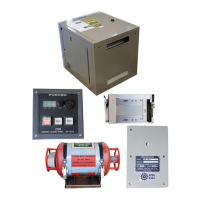
2.11 Junction Box IF-8530 (Option)
When the junction box IF-8530 is connected to the VDR, update the program version
of the junction box to ver. 2450113-01.01 or later. To update the program, prepare the
items shown in the table below.
The items above and IF-8530 is included in the optional IF-8530 version up kit (OP24-
48).
2.11.1 Location of connectors
Connect the serial, analog and digital signals to the terminal boards or connectors in
the junction box. Use the 2.5 mm
2
or AWG14 wires to connect the signals.
For serial and analog signal input, the DIP switch setting is required (see
section 2.11.2).
Item Description
Update program Download it from Furuno Technet.
Cable between a PC and
junction box
Type: JEC9-XH4-#26-L2500, Code No.: 000-170-945-10
Manual for how to update
the program
Type: C42-01406-*, Code No.: 000-190-046-1*
DC 24V IN
CH1-CH4 CH5-CH8
CH9-CH12 CH13-CH16
CH17-CH20 CH21-CH24
CH25-CH28 CH29-CH32
CH33-CH36 CH37-CH40
CH41-CH44 CH45-CH48
CH49-CH52 CH53-CH56
CH57-CH60 CH61-CH64
CH3 CH4 CH5 CH6 CH7 CH8 CH1 CH2
CH1-CH4 CH5-CH8
CH9-CH12 CH13-CH16
DCU
CH1
Serial channels
Digital
Channels
Analog
channels
Location of connectors
DIP switch (from left):
S5 (Keep the default)
S4 (Baud rate 1)
S3 (Baud rate 2)
S2 (Analog 1)
S1 (Analog 1)
CH1: No use.
 Loading...