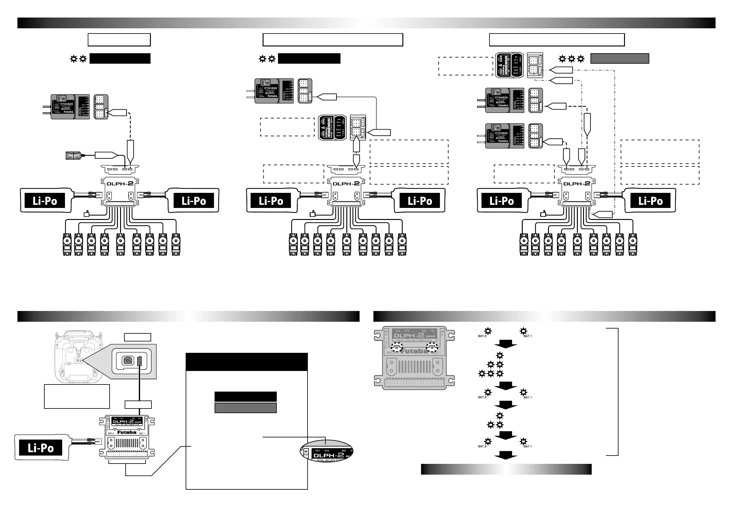
Connection example for each applicationConnection example for each application
This is an example of using one receiver and two batteries.
Deal with battery problems. Since the dual RX function is not
movable, it does not correspond to any reception troubles.
The mode change of DLPH-2 is done by connecting to the S.I/F connector
of the compatible transmitter. The setting method is described in the update
manual of the compatible transmitter.
Connect the DLPH-2 to the compatible transmitter's S.I/F
connector and change the mode.
Connect the DLPH-2 to the compatible transmitter's S.I/F
connector and change the mode.
Connect the DLPH-2 to the compatible transmitter's S.I/F
connector and change the mode.
The battery LED display at startup informs
you of the current status of the DLPH-2.
Here is an example using one receiver, two batteries, and an
airplane gyro GYA553. Deal with battery problems. Since the
dual RX function is not movable, it does not correspond to any
reception troubles.
Here is an example using 2 receivers, 2 batteries and an airplane
gyro GYA553. Deal with battery problems. The dual RX
function is activated to deal with any possible reception troubles.
Single receiver
DLPH-2 voltage sensor
cannot be used.
DLPH-2 voltage sensor
can be used.
Do not connect servos
to GYA553.
Do not connect servos
to GYA553.
Telemetry sensors cannot be
used in this mode.
Telemetry sensors cannot be
used in this mode.
Use the PWM output change
mode of DLPH-2 as it is 1-16ch +
DG1, DG2.
Use the PWM output change
mode of DLPH-2 as it is 1-16ch +
DG1, DG2.
Single receiver+Airplane gyro GYA553 Dual receiver+Airplane gyro GYA553
S BUS.2
S BUS.2
SB/R2
RX1
SB2
SB2
SB2
S.BUS
Single receivermode Single receivermode Airplane gyro mode
DLPH-2 mode changeDLPH-2 mode change Battery LED display at startupBattery LED display at startup
Compatible transmitter
Corresponding to the
corresponding update
Requires power supply to
DLPH-2.
1. Change setting mode
● Dual RX mode (default setting)
●
●
● 1-16ch+DG1,DG2 (default setting)
● 17-24ch+DG1,DG2
This PWM port can be changed from
1-16CH+DG1,DG2 (default setting) to
17-24CH+DG1,DG2.
*9CH~16CH ports cannot be used.
2. PWM output change
RX1 port
Functions that can be changed with
compatible transmitters
1 flashes:Dual RX mode
2 flashes:Single RX mode
3 flashes:Airplane gyro mode
1 flashes:1-16CH+DG1,DG2 mode
2 flashes:17-24CH+DG1,DG2 mode
Both lit
Both lit
Both lit
When using single receiver + Airplane gyro GYA553
or airplane gyro mode, use 1-16ch + DG1, DG2 as
they are.
S.I/F port
Battery LEDBattery LED
The battery LED on the side being used lights up. It turns o when each
becomes 6 V or less.
RX1 SB/R2
Airplane gyro mode
Single receivermode
*For GYA553 SB/R2 output switching, refer to
the GYA553 instruction manual. (used in SB)
*For GYA553 SB/R2 output switching, refer to
the GYA553 instruction manual. (used in SB)
SB2
RX1
SB2
RX2
SB2
During this time, both LEDs will be lit
regardless of battery voltage or number
of connections.
To monitor the battery, check the LED
display after this.
*17-24ch+DG1,DG2
CH3→CH19
*FASSTest26CH cannot be used when using
GYA553.
*FASSTest26CH cannot be used when using
GYA553.
 Loading...