User Manual of AMC4030 Motion Controller
AMP4030 controller,1pc;
USB cable,1unit
Warranty card,1pc
Product Qualified Card,1pc
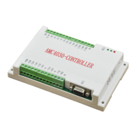
2.2 AMC4030 Interface definition
Table 2-1 Interface Definitions
2.3 AMC4030
Interface Circuit
1)
Connect the controller to the drive (stepper driver or servo drive)
The default output mode for each axis of the AMP4030 is pulse / direction mode. The user can
set the output mode to dual pulse mode via the interface function (see the Programming Manual
for details).
Signal Descriptions Signal Descriptions
PE CAN Signal Ground 5V Power output DC5V
CAN1_H
CAN1 High-Level Signal DIR1 X-axis direction
CAN1_L
CAN1 Low-level Signal PUL1 X-axis pulse
CAN2_H
CAN2 High-Level Signal 5V Power output DC5V
CAN2_L
CAN2 Low-level Signal DIR2 Y-axis direction
ORG1 X-axis
Original position signal
PUL2 Y-axis pulse
ORG2 Y-axis
Original position signal
5V Power output DC5V
ORG3 Z-axis
Original position signal
DIR3 Z-axis direction
GND
Original point signal ground
PUL3 Z-axis pulse
IN1
General input port
1 OUT1
General output port
1
IN2
General input port
2 OUT2
General output port
2
IN3 General input port 3 OUT3 General output port 3
IN4
General input port
4 OUT4
General output port
4
24V_IN
24V Power input USB MINI USB, connect PC
GND 24V Power ground COM
COM,connect HMI
 Loading...