2
Structure
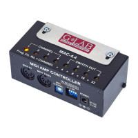
On the inner side of the instruction cover are placed the pictures with elements
numerated below.
1 - Effect ON/OFF footswitch
2 - A reverb LEVEL (intensity) control
3 - A reverb TIME control
4 - Effect switching on indicator
5 - “A” reverb switching on indicator
6 - reverb type selection 1 or 2
7 - output signal connector (OUT)
8 - 9V DC power supply connector
9 - FOOT PEDAL connector
10 - input signal connector (IN)
11 - signal overdrive indicator (PEAK)
12 - B reverb switching on indicator
13 - B reverb LEVEL (intensity) control
14 - B reverb TIME control
15 - Reverb A / reverb B footswitch