Alarms Controller
2
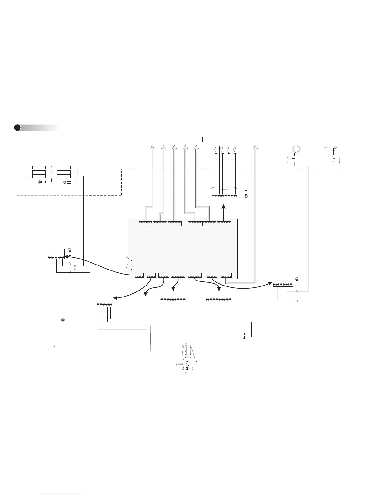
AUXILIARY
OUTPUT 1
(28Vdc, 3A max)
0V
+V
Polarity
unimportant
TAMPER SWITCH &
POWER INDICATOR
Connect to AC MONITOR
terminal block on Power Supply
Board (if used). If this connection
is not made, a "Power Fail"
alarm will be generated at the
PC each time the controller re-
starts.
Ground
Cabinet
Power Supply (see
the Access Control
Design Guide)
4+
4-
2-
3-
1-
4+
2+
3+
1+
Cabinet
1500ft (500m)
max; 24AWG
4 3 2
1
MONITOR
POINTS 1 TO 4
AUXILIARY
OUTPUT 2
(28Vdc, 3A max)
Connect to Normally Open
(NO) or Normally Closed
(NC), as appropriate.
Set address
(See Step 1)
Setting LK1 to position 1
(ON) causes auxiliary
output 1 to energize while
any monitor point enabled
in the SMS software is in
an alarm state
If applicable, ensure
that auxiliary outputs
are noise suppressed.
0V
+V
1C
1NO
2C
2NO
2NC
1NC
Cabinet
AUXILIARY
OUTPUTS 3 & 4
Looping Terminals Looping Terminals
For future use
AC MON+
AC MONITOR
+
-
Ground one
end only
Database
unit
Door/Alarms
Controller
0V 0V
COMMS-
COMMS+ COMMS+
COMMS-
3000ft (1km) max; Belden 9502
Twisted pair
Cabinet
COMMS+
COMMS-
0V
+1 2 V
AC MON-
TMPR
TMPR
MONITOR
POINTS 5 TO 24
0V+12Vdc
Power supply
input
Make sure the building
ground is connected to a
ground stud in the cabinet.
Connect to ac input of
Power Supply Board
(polarity unimportant)
+
-
These terminals are internally
linked and voltage free. They
are not connected to any
other part of the PCB.
These terminals are also
internally linked and voltage
free. They are not connected
to any other part of the PCB.
Power Supply (see
the Access Control
Design Guide)
Short tamper
terminals if a
tamper switch
is not used.
Connection Details
2
CONNECTIONS TO DATABASE UNIT AND OTHER
OPTIONAL REMOTE DOOR/ALARMS CONTROLLERS
Notes:
1). Consult local AHJ (Authority Having Jurisdiction) when installing access control
readers and locking mechanisms to any portal in an egress path.
2). The use of Fail Closed / secure configuration shall be determined by local building
codes and the local AHJ.
3). Wiring methods shall be in accordance with NEC (National Electrical Code)
ANSI/NFPA 70.
4). This device must be installed within the secure area / perimeter for UL1076 and
UL294 Listed installations.
5). Installer must provide Network Surge Protection by installing (per manufacturers
installation instructions) 1 each APC PNet1GB Ethernet surge protection device in line
with the RJ-45 Ethernet connector on this board prior to connecting this board to the
local or wide area network.
6). For Access Control Systems in a “Stand Alone” configuration only, the following
Power supplies are to be installed: Model MN-PSU-KIT-MKII with MN-TRANS-75-UL
transformer. Any additional power supply used (e.g. for door releases and auxiliary
outputs) must be power limited, UL listed for Access Control Systems and Accessories.
All interconnecting devices must be UL Listed.
7). Some devices described in these instructions may not be applicable for sites
requiring UL compliance. Please refer to the M2150 Access Control Design Guide for
details of the controllers, modules and features that have been UL tested for use with
this device.
WARNING: Incorrect connections will
permanently damage the board.
Note: UL compliance requires power-
limited and non-power-limited wiring
to be separated by at least 0.25”
(7mm). Please refer to the cabinet
installation instructions.

 Loading...